
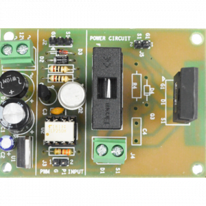
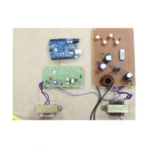
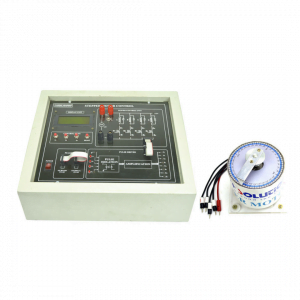
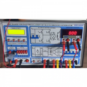
 CONTROL POWER MODULE")


Description
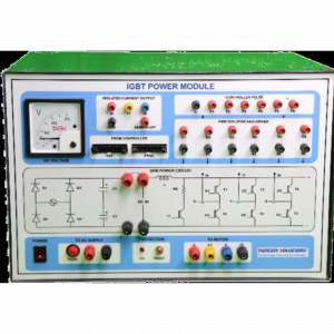
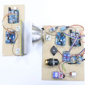
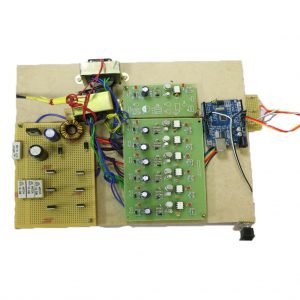
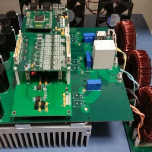
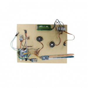
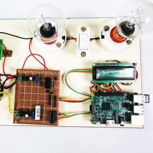
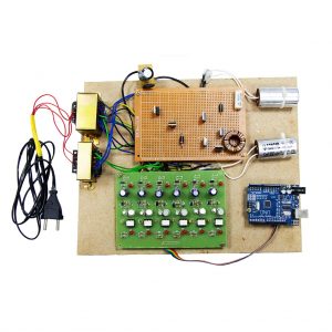
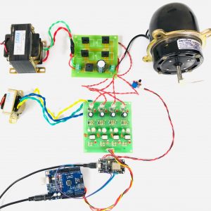
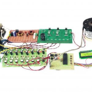
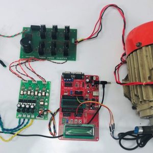
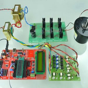
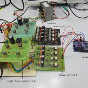
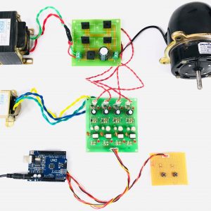
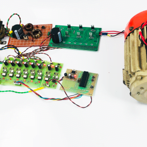
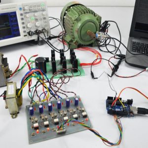
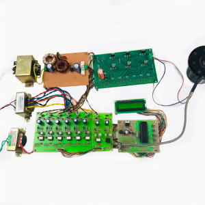
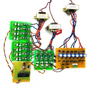
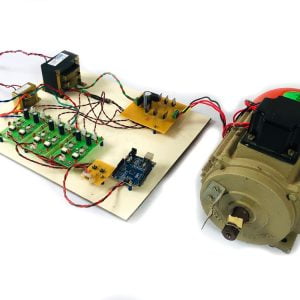
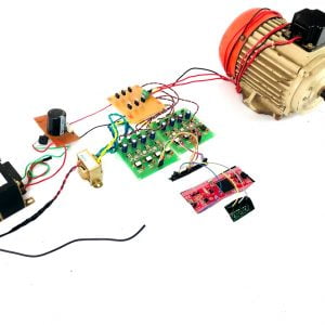
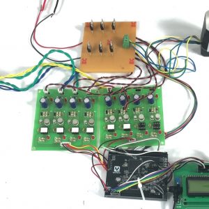
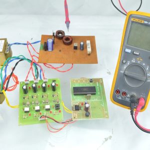
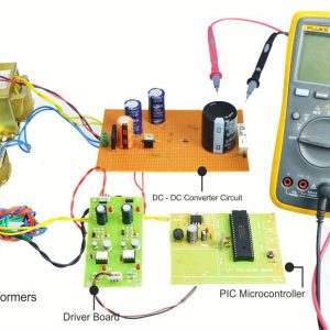
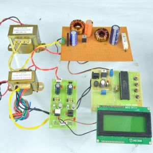
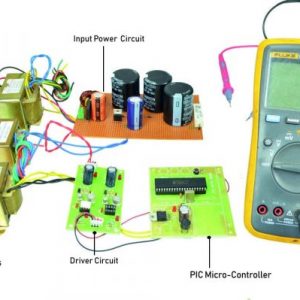
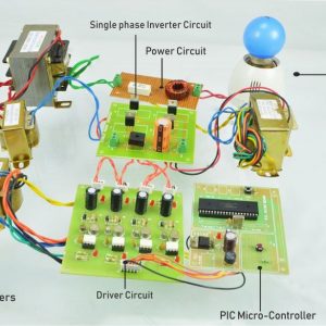
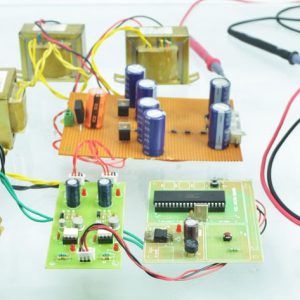
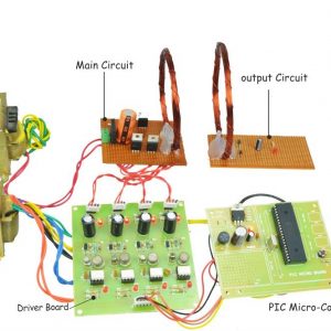
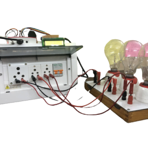
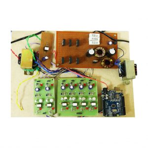
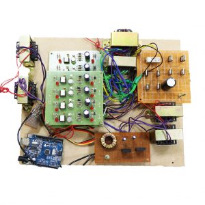
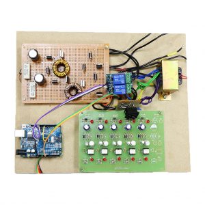
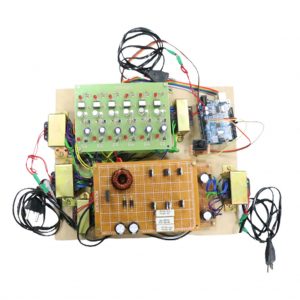
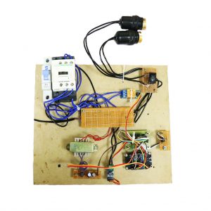
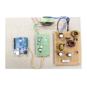
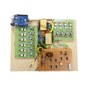
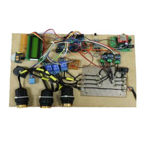
This Power Converter Module has Controller, Asymmetric Bridge Converter (with Driver Module), Protection Unit, Rectifier Unit, Load Current Sensing Unit, SR-Motor with Sensor Unit.
Here SR-Motor can be controlled in Open Loop & Closed Loop operation (speed), Forward & Reverse Running Operation. Technique used to Control the SR-Motor is PWM. Provision to get the data of Inductance Profile to generate Pulse. 3 or 4 Phase SR-Motor Can be Controlled.
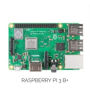
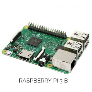
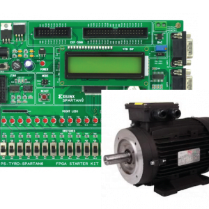
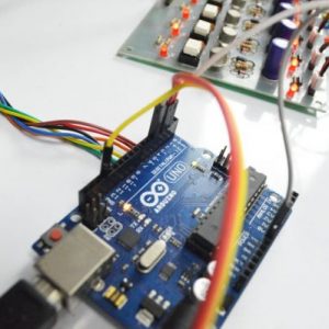
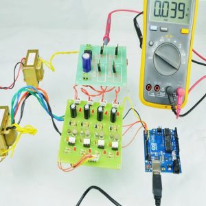
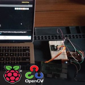
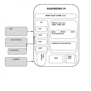
External various PWM Techniques can be implemented from various External Controllers like DSPIC, DSP, FPGA, ARDUINO, RASPBERRY Pi, PIC, 8051, etc…
FEATURES
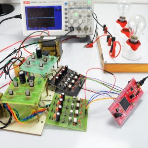
- DSO can be used to analyze the pulse and waveforms.
- External Various PWM techniques Can be applied from Various Controllers.
- OVL or SC Reset and Fused Protection for the Main Power Circuit with Visibility and Sound indication.
- Isolated Load Current Waveform termination.
- Controlling action Display Unit with Controlling Keys.
- Sensor enabling Indication.
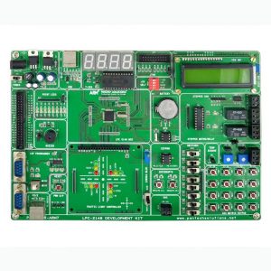
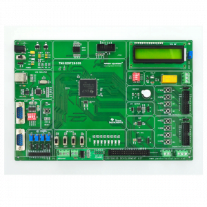
CONTROLLER
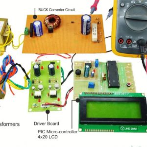
- Microchip based dsPIC30F4011 16 Bit digital signal controller operating at 33nS, On chip-motor control peripherals 6 motor control PWM with programmable dead band, quadrature encoder interface.
- 4 no. of switches are provided to control the motor speed by varying Duty Cycle.
- Selection of two modes of operation (Open or Closed Loop). Selection of Forward & Reverse Running Mode.
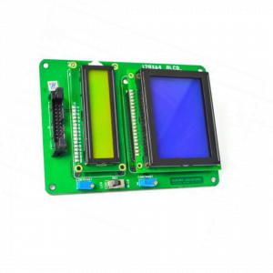
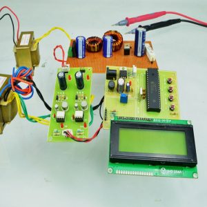
- 1 No. of LCD provided to display the controlling action.
Memory
- 48K Flash program Memory
- 2 K RAM for data memory
- 1K EEPROM memory
Additional features
- DSPIC30F4011 Controller all peripherals can be learned and get trained (e.g.: Capture, ADC, Interrupt, LCD, PWM, SPI, CAN, UART
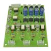
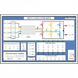
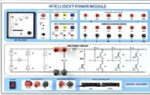
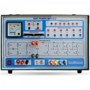
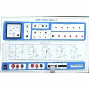
SRM POWER MODULE
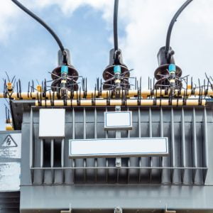
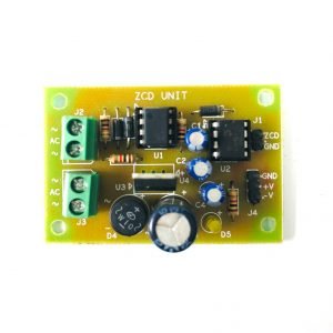
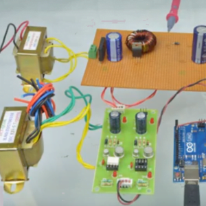
Rectifier Unit
- 1 no of Single-Phase Diode Bridge Rectifier (230V, 10 Amps) with filter capacitor provided for input AC rectification and fed as input to power circuit with fuse protection, OVL Protection and SC Protection.
- 1 no of analog DC Voltmeter provided for Voltage measurement.
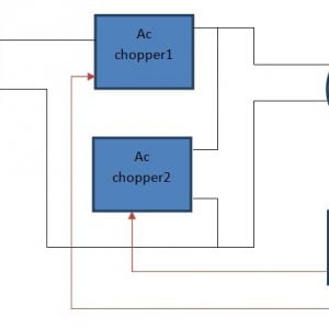
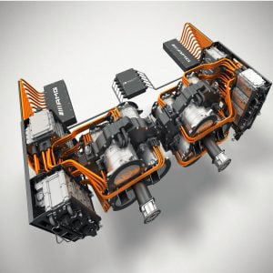
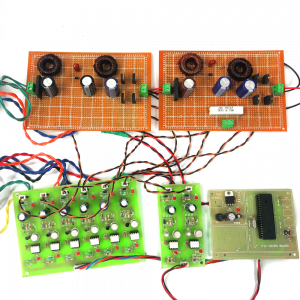
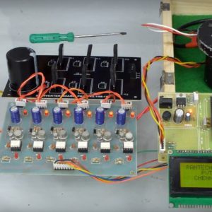
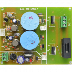
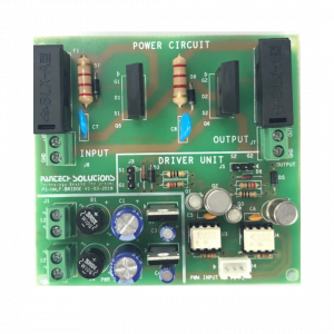
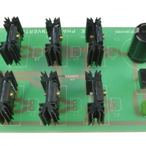
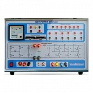
Asymmetric Bridge Converter Module
- 8 No`s of IGBT K40T120 (Soft, Fast Recovery) Device with Heatsink forms the Power Circuit.
- Rating of device is 1200V / 40 Amps @ 100°C.
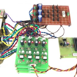
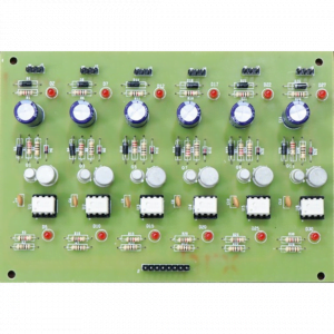
Driver Unit
- 8 No’s of high speed Opto-Isolated Gate Pulse and Amplification provided for PWM isolation from the controller Unit.
- Isolated +15V @1Amps provided for Driver IC.
- Supported Frequency 25Khz.
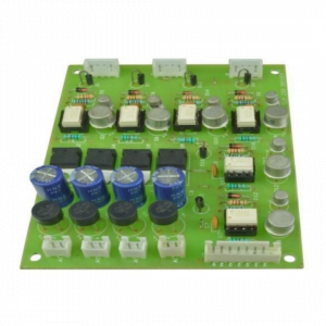
Protection Unit
- 4 No of Hall Effect Current Sensor provided for Load current Waveform for Protection Unit.
- 1 No of LED and Buzzer to indicate Trip status of OVL or SC Protection enabled.
- 1 no. of OVL or SC Release switch provided to reset the TRIP function.
Test Points Unit
- 4+1 No’s of test points provided for Controller PWM.
- 4 No’s of test points provided for Isolated Load Current waveform analysis.
- 4 No`s of Rotor Position Sensor test points with Indication of LED.
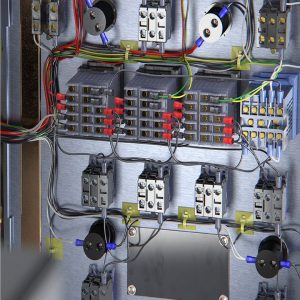
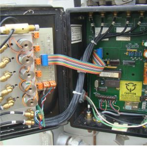
Box Fabrication Unit
- All are mounted in attractive powder coated cabinet with sticker front panel with mimic diagram about Main Power Circuit.
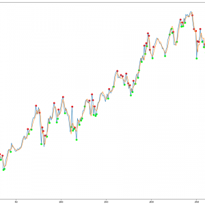
INDUCTANCE PROFILE
Provision is provided to get data for the Inductance Profile graph. This profile helps to
Experiments:
- Study on DSPIC30F4011 Controller all peripherals.
- PWM Generation.
- Study on SRM POWER CIRCUIT for SR-Motor.
- Study on Controlling of SR-Motor in Open Loop.
- Study on Controlling of SR-Motor in Closed Loop.
- Study on Forward and Reverse Running of SR-Motor.
- Inductance Profile Table & Graph.
- Load Vs Speed Characteristics.
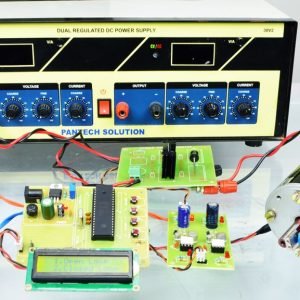
POWER Required
- 1Phase AC : 230V/5A/50Hz
- AC Adaptor : 9V AC/50Hz
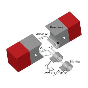
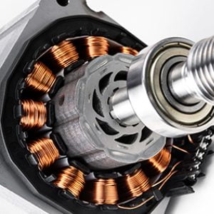
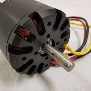
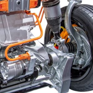
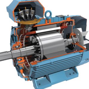
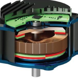
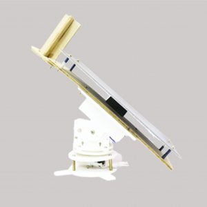
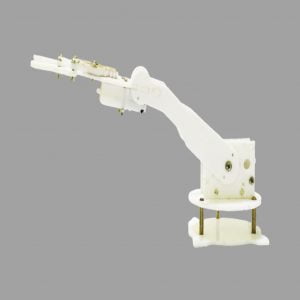
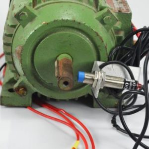
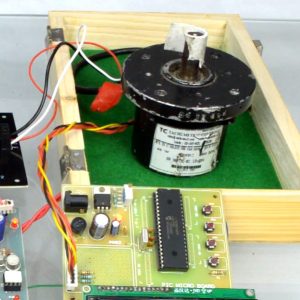
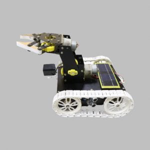
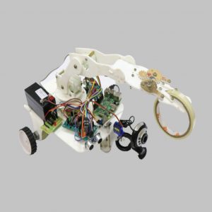
SR-Motor SPECIFICATIONS
- POWER : 1 HP (0.75 KW)
- Voltage : 230V DC
- Type : 8/6Pole 4Phase (6/4, 3Ph)
- Speed : 3000 RPM
- Rotor Position Sensor with cable connector
BUNDLE CONTENTS
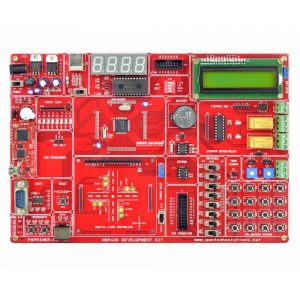
- DSPIC30F4011 Development Board
- SRM POWER MODULE
- SR-Motor with Load Setup and Degree Punched.
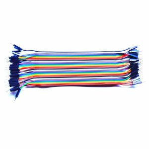
- Patch Cords, 3Pin Power cord
- FRC Cable, 9VAC Adaptor
- RS232 cable
- User Manual, Working Video
- MPLAB Software Support
- MATLAB Simulink Model File
- 3A Fuse (Extra)
Equipment’s Need to Function this Trainer Kit
- Single Phase Auto Transformer (0-230V)/5A
- DSO is Preferred for Waveform Analysis
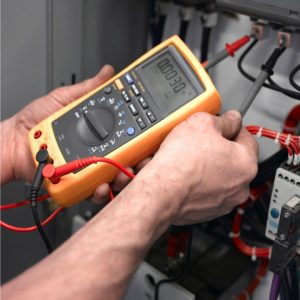
- Multimeter
- LCR Meter for Inductance Measuring


Customer Reviews
There are no reviews yet.