


Description
Zeta Converter Using Arduino
Abstract:
In most PV applications used Zeta converter is used for a buck or boosts the input voltage. The solar panel voltage is small, so the output voltage of the solar panel is applied to the converter and increases the input voltage by using this converter. The duty cycle of the converter is varied by Arduino controller. The duty cycle is varied, the output voltage of the converter also varied.
Zeta Converter Using Arduino
Introduction:
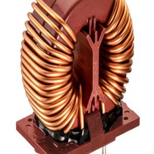
The Zeta converter is a DC to DC converter. The dc to dc converter is input voltage is converted into another level of output voltage. An example Zeta converter input voltage is 12v and the output voltage is greater than 12v. They play an important role in renewable energy sources such as solar energy, hybrid vehicle systems, etc. Zeta converter is a class of switched-mode power supply. It consists of at least two semiconductor switches and at least one energy storage element such as a capacitor or inductor or a combination of both.
Proposed System:
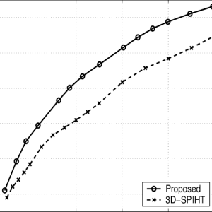
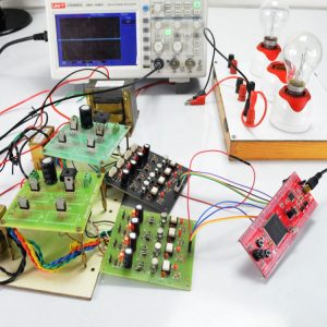
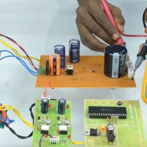
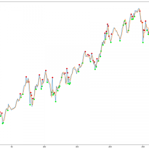
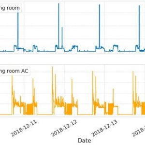
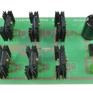
The Zeta Converter input voltage is boosted or increased and a high voltage appears at the output. A Zeta converter or step-up voltage regulator provides nonisolated, switch-mode dc-dc conversion with the advantage of simplicity and low cost. The Zeta converter output voltage is controlled by using pulse width modulation of switching frequency. The input dc voltage is applied to the inductor and the inductor stores the energy. When the switch is closed the stored energy is supplied to the capacitor and the capacitor is charged. When the switch is opened the capacitor voltage is discharged to a resistive load. The Zeta converter output voltage is shown below.
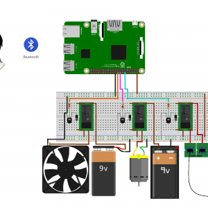
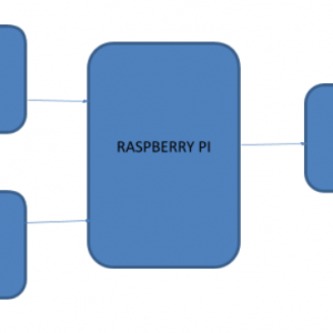
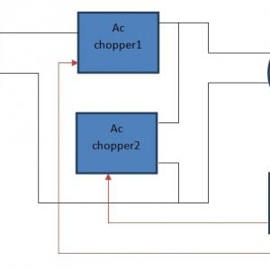
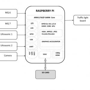
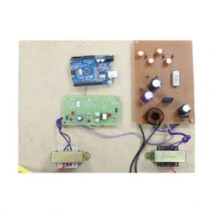
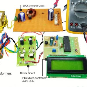
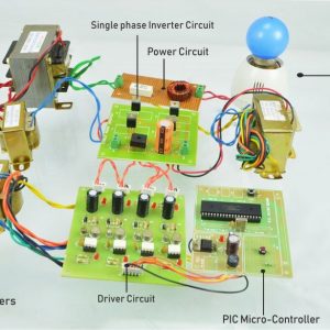
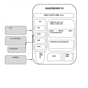
Block Diagram for Zeta Converter Using Arduino

Block Diagram Explanation:
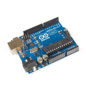
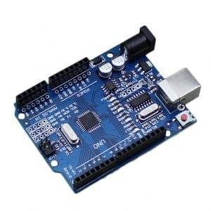
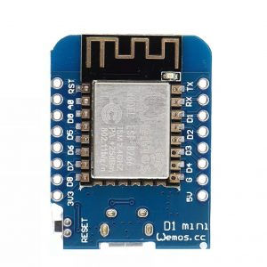
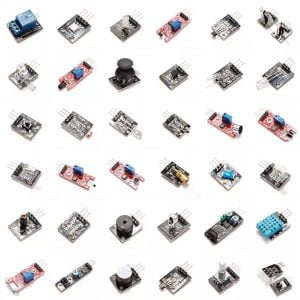
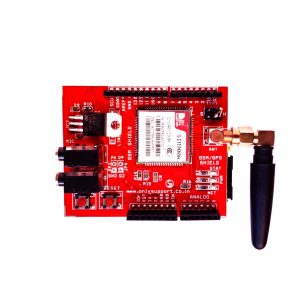
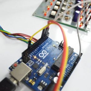
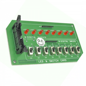
- Pulse generator: ? Here we have used the Arduino Uno controller to generate a PWM signal.
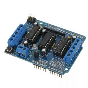
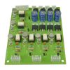
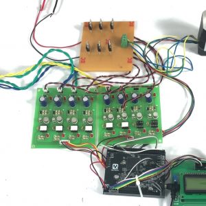
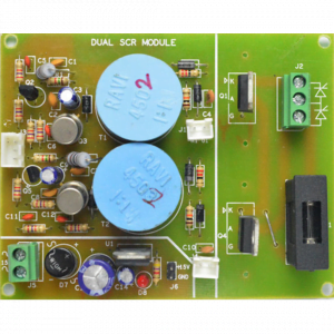
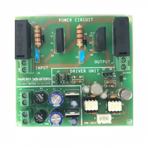
- Driver circuit: It is used to amplify the pulses and provided isolations using an optocoupler. It has two functions,
- Amplification
- Isolation
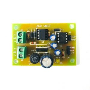
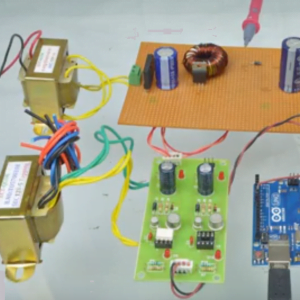
- Bridge Rectifier: ?It converts AC supply into DC Supply.
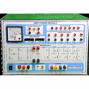
- Zeta converter: ?It converts low voltage DC into high voltage DC supply.
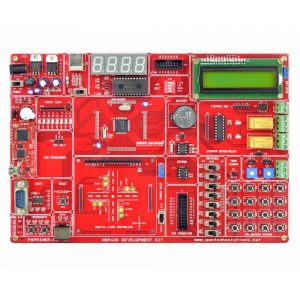
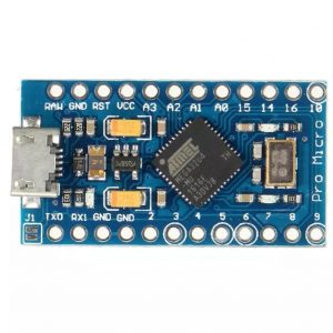
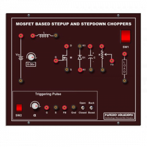
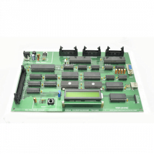
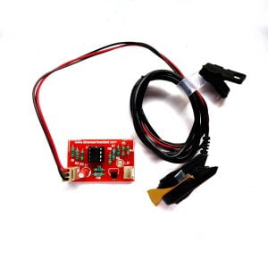
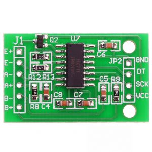
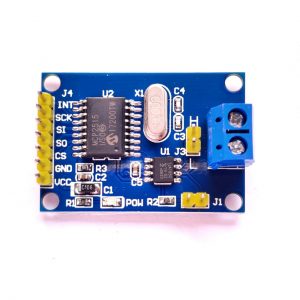
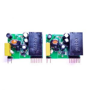
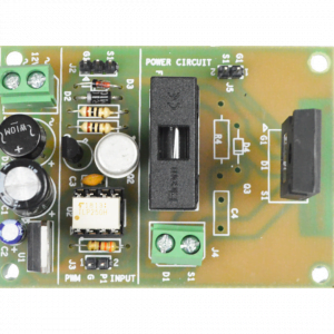
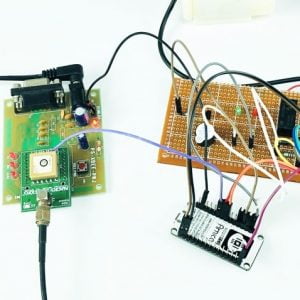
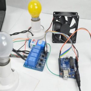
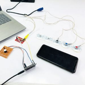
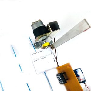
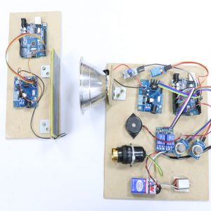
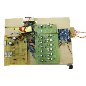
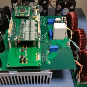
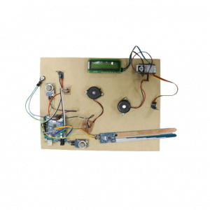
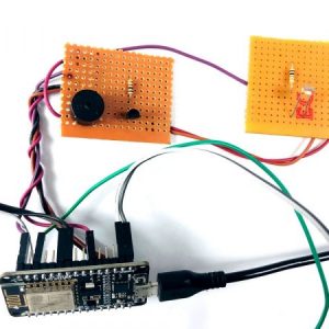
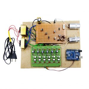
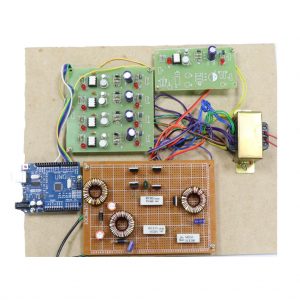
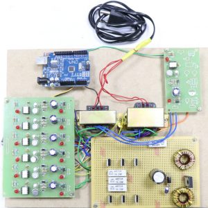
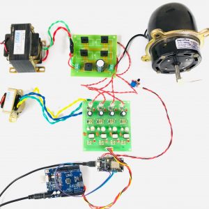
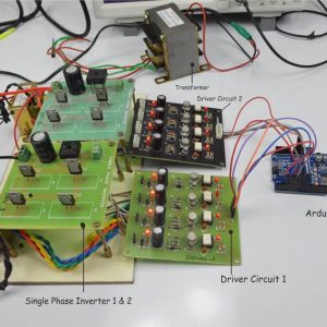
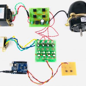
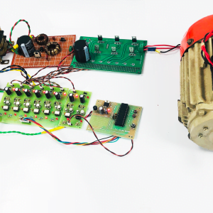
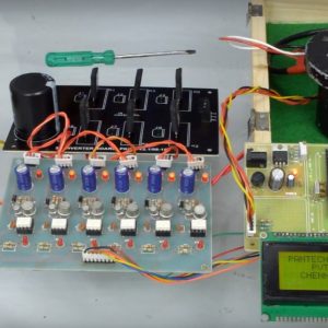
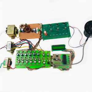
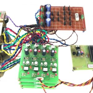
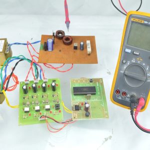
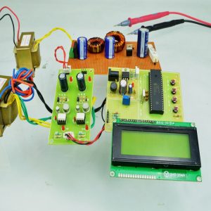
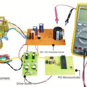
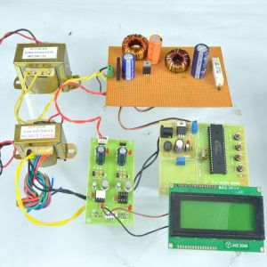
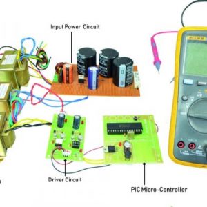
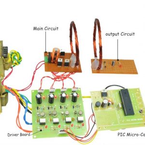
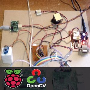
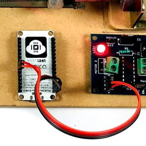
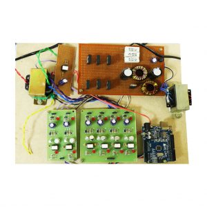
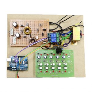
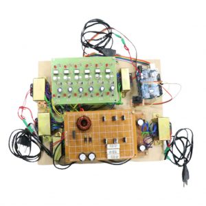
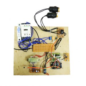
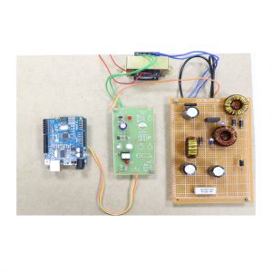
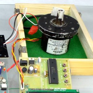
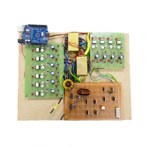
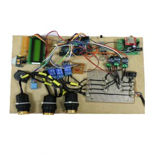
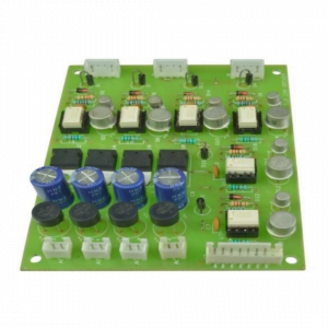
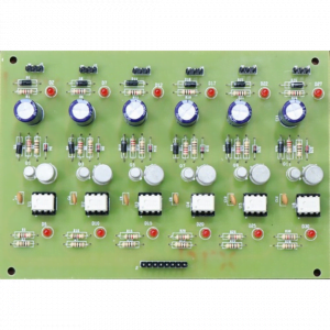
Driver Board

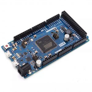
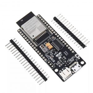
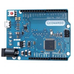
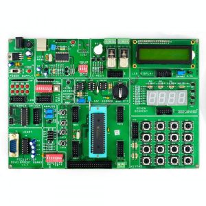
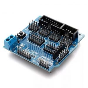
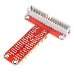
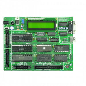
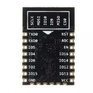
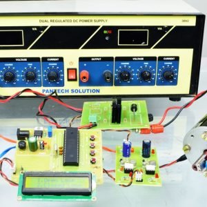
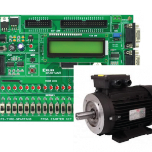
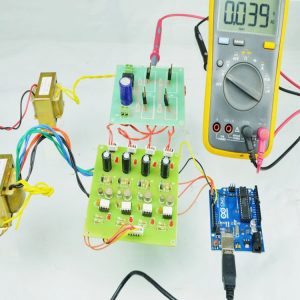
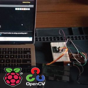
Arduino Controller

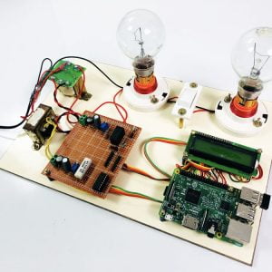
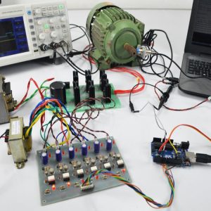
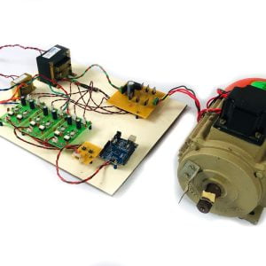
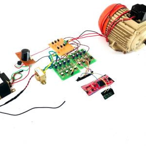
Working:
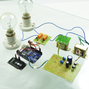
The Arduino controller is used to generate the PWM pulses for the converter circuit. The Arduino controller pulses are given to the driver circuit as input. Driver board is mainly used to isolate and amplify the input signals from the controller. The amplified driver output is connected to the main power circuit devices. The ac supply is converted into dc by using a bridge rectifier. And the dc voltage is boosted by the Zeta converter. That dc voltage is applied to a resistive load and duty cycle of the converter is varying the output voltage also varied.
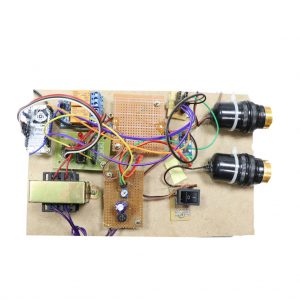
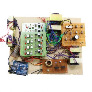
Circuit Diagram For Zeta Converter:


Advantages:
- High efficiency
- Low cost
- Simple construction
Applications:
- Dc to Dc converter
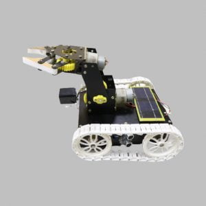
- PV applications
Conclusion:
Zeta Converter is an efficient step-up DC-DC converter that is used in numerous electronic devices. A closed-loop model is developed and used successfully. This converter has advantages like reduced components, high performance, less weight, and accuracy. The converter output depends on the duty cycle of the converter.


Customer Reviews
There are no reviews yet.