


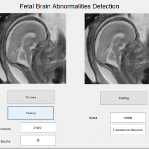
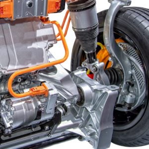
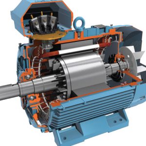
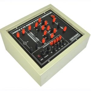
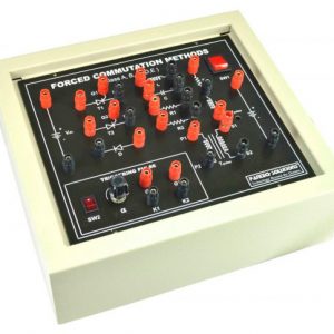
Description
Power Factor Improvement In Modified Bridge less Landsman Converter Fed EV Battery Charger
Objective
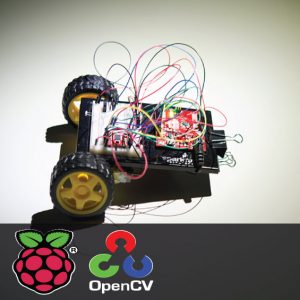
Power factor improvement in modified bridge less landsman converter fed EV battery charger has been developed and operation of the charger has been verified by the experimental results under steady-state and sudden fluctuations in input voltage. The results from the hardware validation show that the performance of the proposed charger is found satisfactory for improved power quality-based charging of EV battery.
Power Factor Improvement In Modified Bridge less Landsman Converter Fed EV Battery Charger
Abstract:
An improved EV charger with a modified bl landsman converter followed by a fly back converter has been proposed, analyzed, and validated in this work to charge an EV battery with inherent pf correction. The design and control of the proposed EV charger in DCM mode have offered the advantage of the reduced number of sensors at the output. Moreover, the proposed bl converter has reduced the input and output current ripples due to inductors both in the input and output of the converter. Power Factor Improvement In Modified Bridgeless Landsman Converter Fed EV Battery Charger Power Factor Improvement In Modified Bridge less Landsman Converter Fed EV Battery Charger
Power Factor Improvement In Modified Bridge less Landsman Converter Fed E V Battery Charger
Introduction:
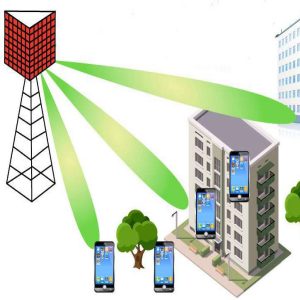
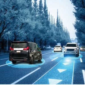
With the strict supervision of emissions, fuel savings, global warming issues, and limited energy resources, the contribution of electric mobility is significant towards the development of sustainable and efficient alternatives in the transport sector. Regarding this, a survey based on the present scenario and future technologies for the propulsion of electric vehicles (EV), is presented, This work deals with the design and implementation of a new charger for battery-operated electric vehicles (BEV) with power factor improvement at the front-end.
The future scope for the proposed work is enlisted as follows.
- the efficiency and power level could be increased to provide fast charging to the battery. Variable frequency control and modular construction approaches might aid in the optimization of the efficiency curve.
- the use of soft switching circuits for further reduction in switch voltage and current stress.
- the input and output ripple could further be reduced using the interleaving of the landsman converter cells.
- the use of wide bandgap semiconductor devices (sic and gan based devices) leads to better converter Efficiency at high power rating owing to reduced voltage drops and switching transition times.
- this work can be extended to control motor drives like bldc and srm motor drive for EV propulsion.
- the proposed design work can be extended to account for the certain dynamic conditions of battery and vehicle which gives a wide platform for future innovation to the researchers. Power Factor Improvement In Modified Bridge less Landsman Converter Fed EV Battery Charger
Power Factor Improvement In Modified Bridge less Landsman Converter Fed EV Battery Charger
Existing system:
- The events are powered up by the rechargeable batteries these batteries are typically recharged using an ac–dc converter known as an EV charger. The most general architecture of an EV battery charger comprises a boost converter at the front end and an isolated converter,
- Interleaved and zero voltage switching (vs) PFC (power factor correction) converter-based battery chargers however, interleaving the PFC converter come with the cost of high current stress in switches.
- Full-bridge topology is prominent for PFC-based EV chargers with the advantages like high power density and high efficiency but the arrangement of four switches makes the charger control complex.
- Llc (inductor–inductor-capacitor) resonant converter offers an attractive solution with high efficiency, low EMI (electromagnetic interference) noise, and a high power density at a wide input range. However, due to added difficulty in the design and analysis process of LLC converter,
- Considering ac-dc conversion as the distinguishing feature of EV battery chargers, many dbr (diode bridge rectifier) fed unidirectional isolated single-stage or two-stage converters without isolation. However, the performance of the conventional charger does not match with the prescribed power quality (PQ) standard IEC 61000-3-2
- An efficient power factor correction (PFC) technique, which eliminates the adverse effects of input db r as well, is needed at the front-end of the conventional dbr fed charger, based on these parameters different converters have been introduced.
- A family of bridge less front-end buck-boost converters is presented from that idea bridge less landsman power factor correction converter preceded
Power Factor Improvement In Modified Bridge less Landsman Converter Fed EV Battery Charger
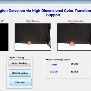
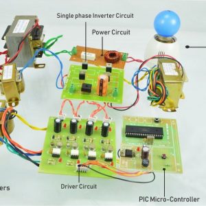
Proposed system:
The proposed landsman converter, at the first stage, is slightly modified than that reported in by rearranging the input and output side inductors. The proposed modification offers the advantage of low input current ripple, due to continuous conduction (ccm) of input inductors lip,n as well as the benefit of low output current ripple with the conventional landsman topology is retained in the proposed topology. Two parallel converters operate in synchronization, and, in a discontinuous region (DCM mode) in the respective half cycles of mains voltage to improve the power factor to unity. The DCM operation offers the inherent benefits of low cost and simplicity in the circuit owing to the use of a single sensor at the output stage. A voltage follower-based proportional and integral (pi) controller is used, effectively, to regulate the intermediate dc-link voltage of the charger. However, the flyback converter at the second stage is controlled using a dual-loop pi controller. The battery current is regulated corresponding to 60% state of charge (soc) to 100% soc with the simple pi control during the conditions of constant current and constant voltage mode charging [33-35]. Therefore, the proposed EV battery charger offers an improved power quality-based charging profile to the EV battery. Moreover, the input power quality indices of the charger, are found within the range as per recommended IEC 61000-3-2 standard. The efficiency is improved as compared to the conventional dbr fed charger due to conduction losses reduced to half in each cycle. Power Factor Improvement In Modified Bridge less Landsman Converter Fed EV Battery Charger
Advantages of the proposed system
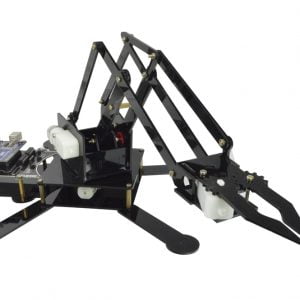
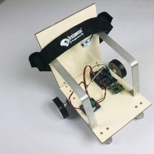
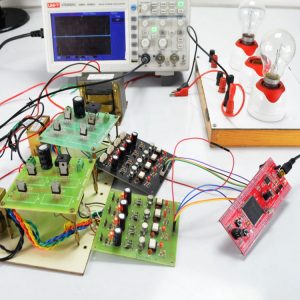
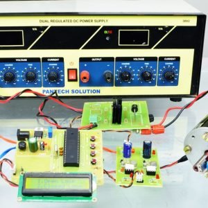
Offers improved power quality, low device stress, and low input and output current ripple with low input current harmonics when compared to the conventional one. Moreover, to demonstrate the conformity of the proposed charger to an IEC 61000-3-2 standard, a prototype is built and tested to charge a 48v EV battery of 100ah capacity, under transients in input voltage. The performance of the charger is found satisfactory for all the cases. Power Factor Improvement In Modified Bridge less Landsman Converter Fed EV Battery Charger
Power Factor Improvement In Modified Bridge less Landsman Converter Fed E V Battery Charger
Application
- Battery operated electric vehicle (BEV)
- Hybrid electric vehicles (HEVs)
Power Factor Improvement In Modified Bridge less Landsman Converter Fed E V Battery Charger
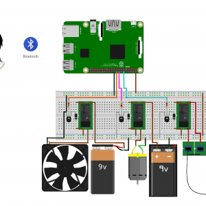
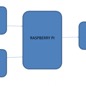
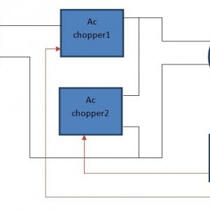
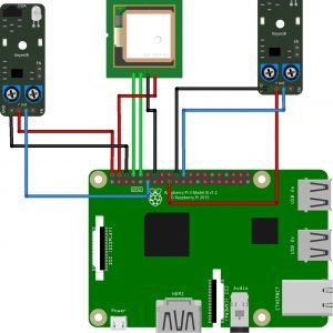
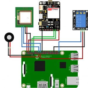
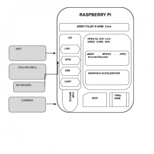
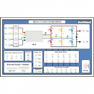
Block diagram

Power Factor Improvement In Modified Bridge less Landsman Converter Fed EV Battery Charger
Block diagram explanation
Input
- Input is ac supply
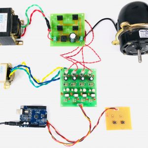
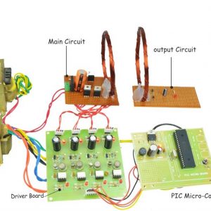
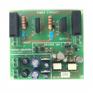
Main circuit
- The main circuit is with two chopper circuits, first one is a landsman converter, power factor correction is being done in this converter followed by the flyback converter
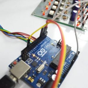
Controller
- The brain of the circuit, which will control all the functions of the circuit, all the modes of this circuit perfectly achieved by the controller
Feedback
- For having a stabilized output closed-loop data has been selected which will transfer the instant values of output data to the controller.
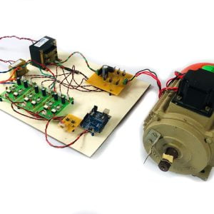
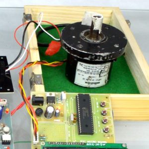
Output
- Output terminals are connected to the batteries of the EV.
Power Factor Improvement In Modified Bridge less Landsman Converter Fed EV Battery Charger
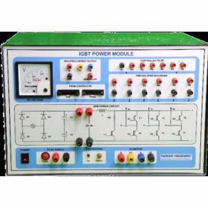
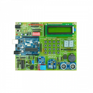
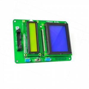
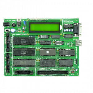
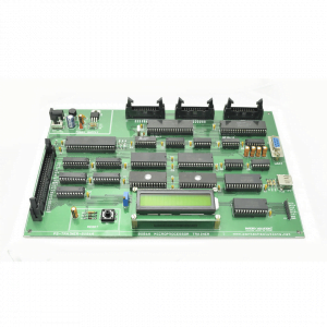
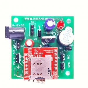
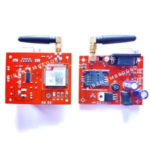
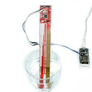
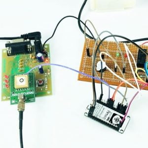
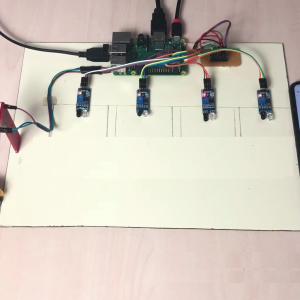
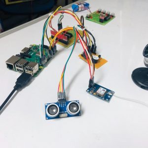
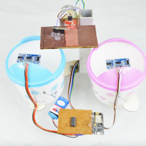
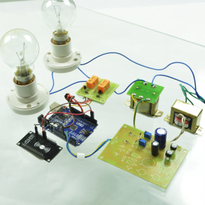
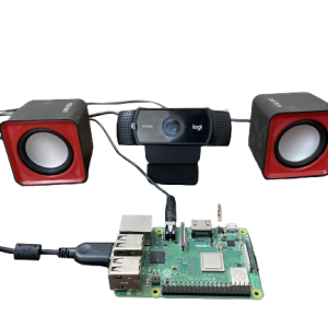
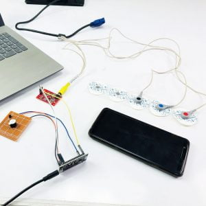
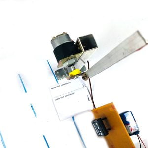
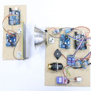
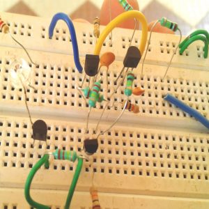
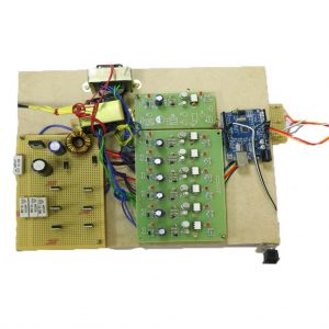
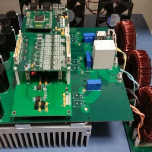
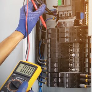
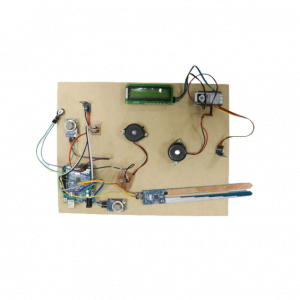
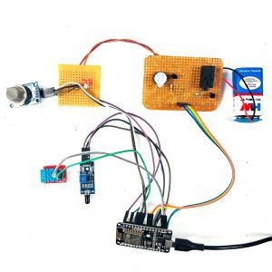
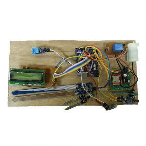
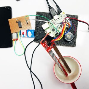
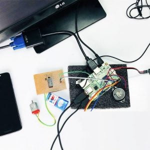
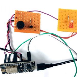
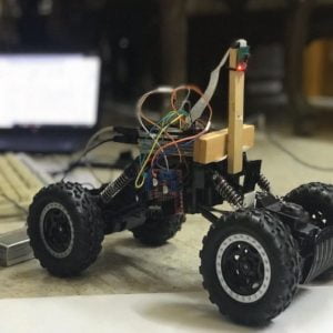
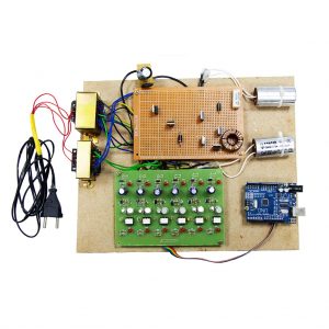
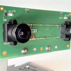
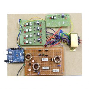
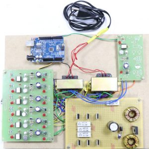
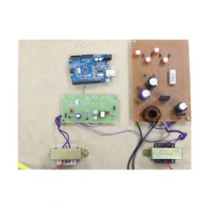
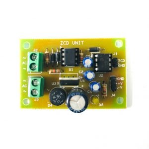
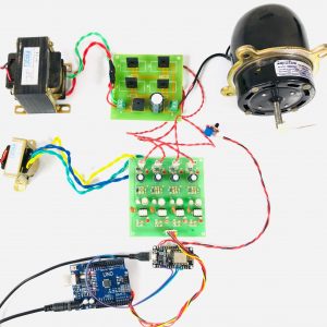
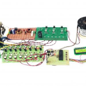
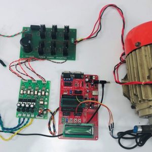
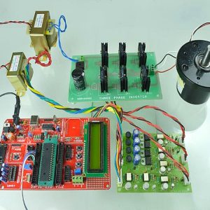
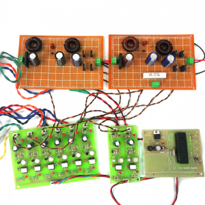
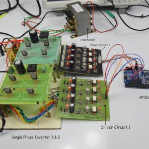
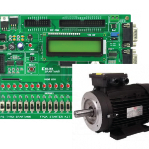
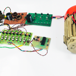
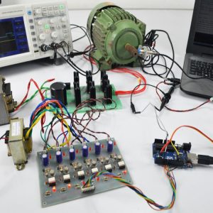
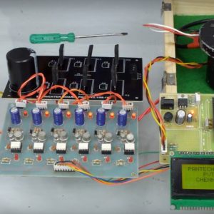
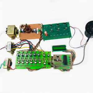
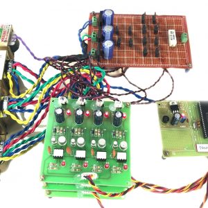
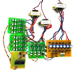
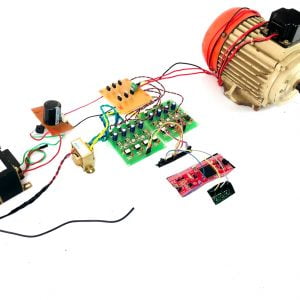
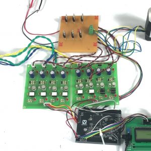
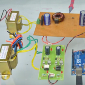
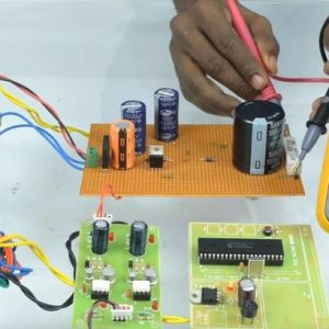
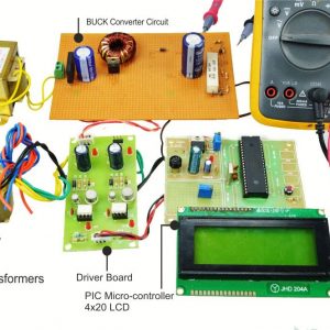
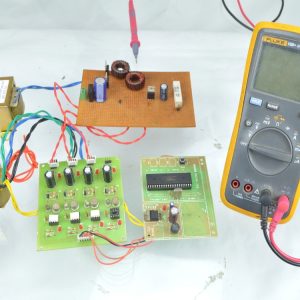
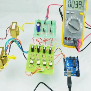
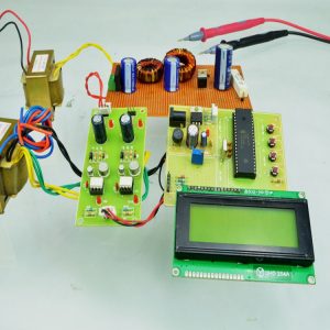
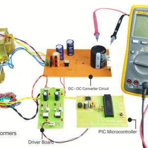
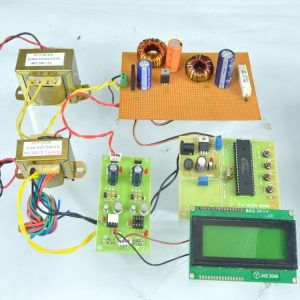
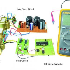
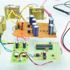
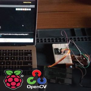
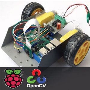
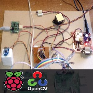
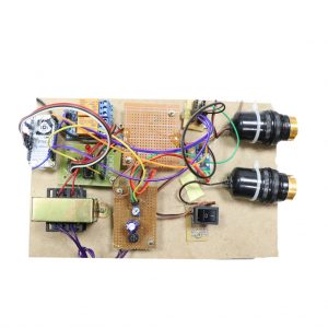
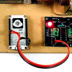
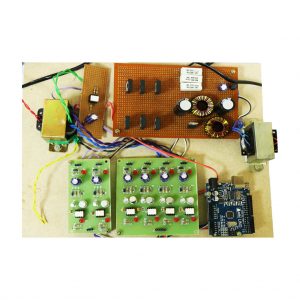
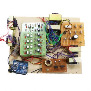
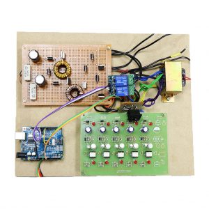
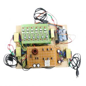
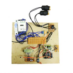
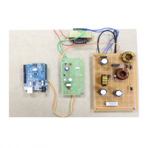
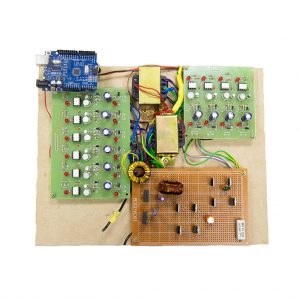
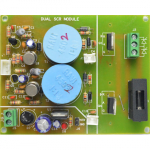
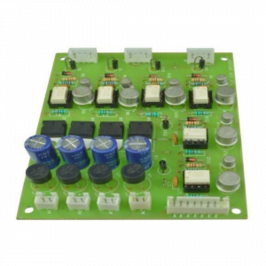
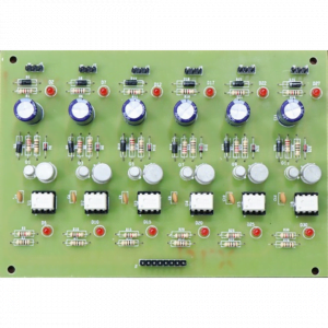
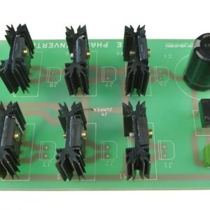
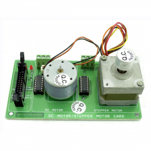
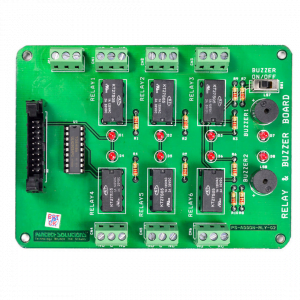
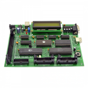
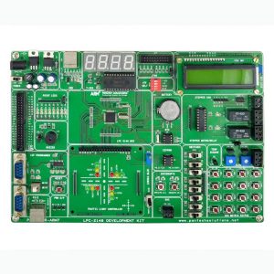
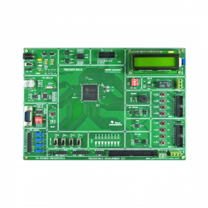
Hardware requirement
- Arduino micro controller
- Circuit components
Input inductor = 4.2mh
Capacitor cp and can = 1.73 uf
Output inductor = 429.21u h
Dc-link capacitor = 1.5mf
Filter capacitor = 580nf
Filter inductor = 1.7mh
Mosfet switches (irf250, irf840)
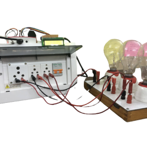
- Input supply
- Output measurement device
Software required
- Arduino ide
- Matlab (Simulink)
References
- Wong Su, Habibullah Michi, wente Zeng, and mo-yuen chow, “a survey on the electrification of transportation in a smart grid environment,” IEEE transactions industrial informatics, vol. 8, no. 1, pp. 1-10, Feb. 2012. Ching
- Chuen chan, “the state of the art of electric, hybrid, and fuel cell vehicles,” proc. Ieee, vol. 95, no. 4, pp. 704–718, Apr. 2007.
- Kaushik rajashekara, “present status and future trends in electric vehicle propulsion technologies,” IEEE j. Emerg. Sel. Topics power electronics., vol. 1, no. 1, pp. 3–10, Mar. 2013.
- Juan c. Gomez and mediate m. Morcos, “impact of EV battery chargers on the power quality of distribution systems,” IEEE transactions power del., vol. 18, no. 3, pp. 975–981, Jul. 2003.
- Luca solo, “nonconventional on-board charger for electric vehicle propulsion batteries,” IEEE transactions vehicular


Customer Reviews
There are no reviews yet.