


Description
Induction Motor Control using SEPIC Converter
Abstract:
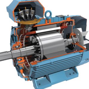
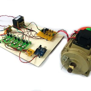
This project is used to control the speed of a three-phase induction motor by employing a sepic converter. The sepic converter is used to boost the input voltage. The boosted dc voltage is applied to the three-phase inverter. This three-phase VSI operates at a 120-degree mode of operation. Three-phase induction motor speed depends on the frequency of the inverter. ( SEPIC converter. is used to boost the input voltage waveforms)
Introduction:
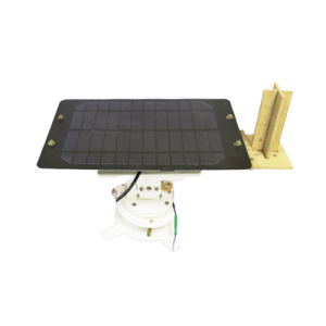
This project is mainly used for renewable energy sources like solar, wind, etc. The solar convert the sunlight directly into electricity. That voltage range is low so that low voltage is boosted by using the converter circuits. The converter is used to convert the low voltage dc into high voltage dc. Solar energy is involved in power plants, homes made appliances, ventilation systems, commercial appliances, solar lighting, cars, and other remote applications where transmission and distribution are done.
Proposed System
The sepic converter has two inductors and one power device for boosting the input voltage. If the power device duty cycle is varying the output voltage of the converter is varied. The converter output dc voltage is applied to the three-phase inverter circuit. It converts the dc voltage into three-phase ac voltage to drive the three-phase induction motor. The PIC controller has a key function for controlling the speed of the induction motor.
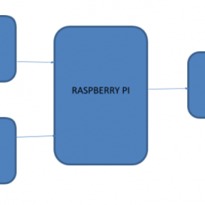
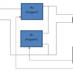
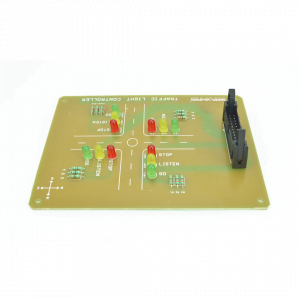
Block Diagram

Block Diagram Explanation:
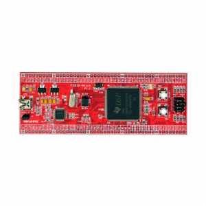
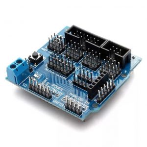
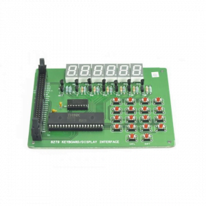
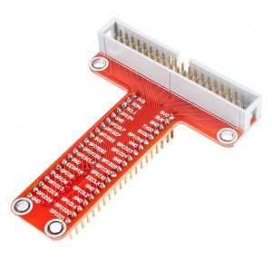
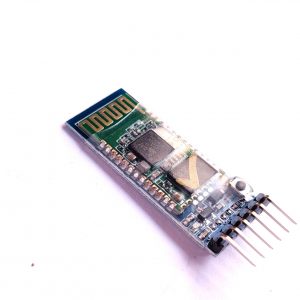
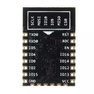
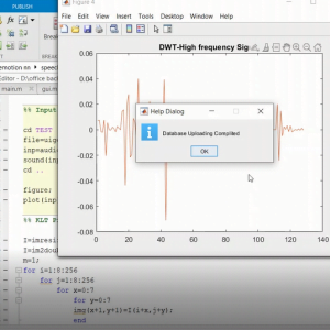
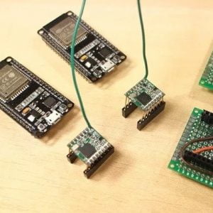
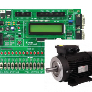
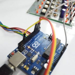
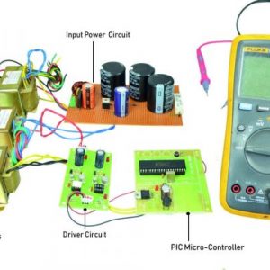
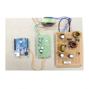
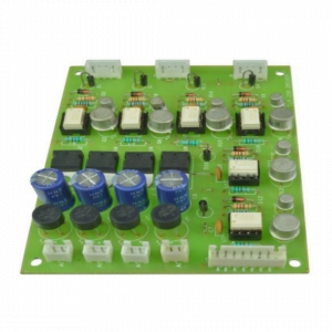
- Pulse generator: ? Here we have used a PIC microcontroller (PIC 16F877a) to generate a PWM signal.
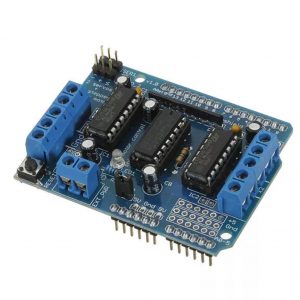
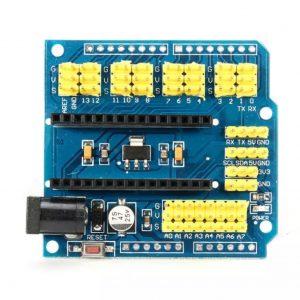
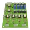
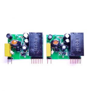
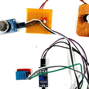
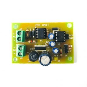
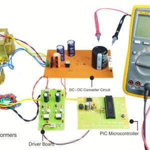
- Driver circuit: It is used to amplify the pulses and provided isolations using an optocoupler. It has two functions,
- Amplification
- Isolation
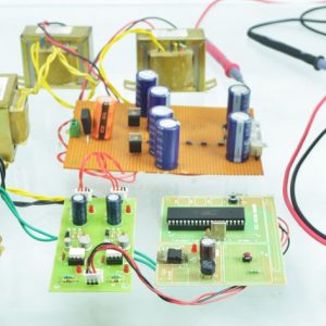
- Bridge Rectifier: It converts AC supply to DC Supply.
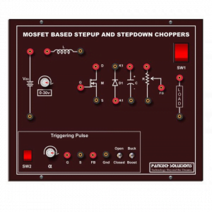
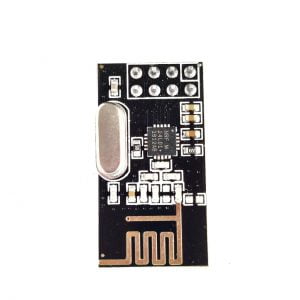
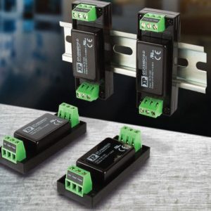
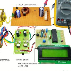
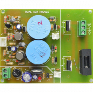
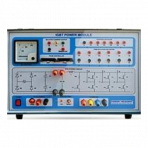
- SEPIC converter: It converts low voltage DC to high voltage DC supply.
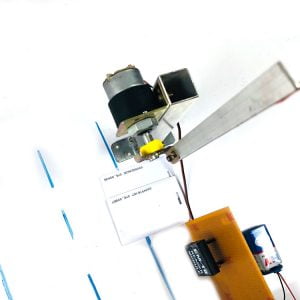
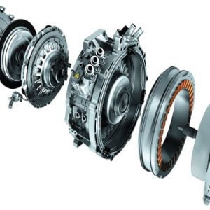
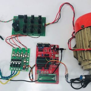
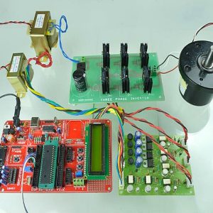
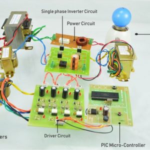
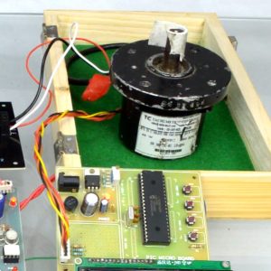
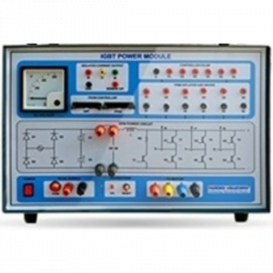
- Three PhaseInverter: It converts DC supply to three-phase AC Supply to drive the three-phase induction motor.
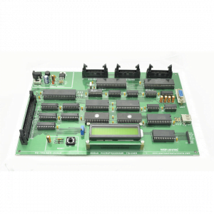
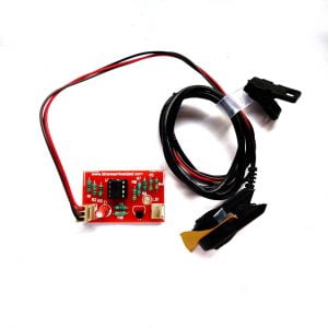
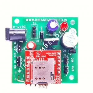
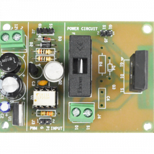
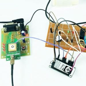
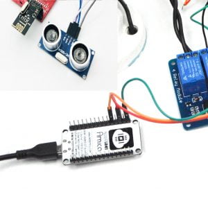
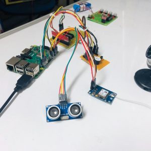
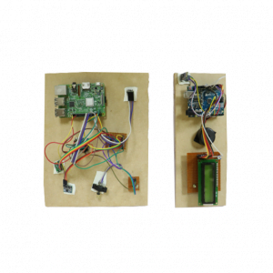
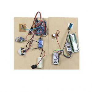
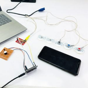
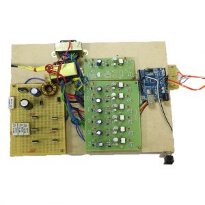
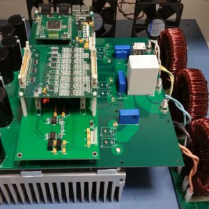
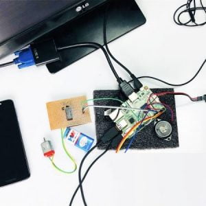
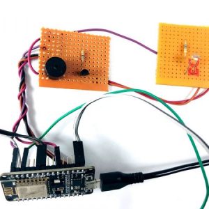
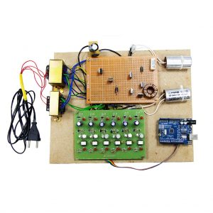
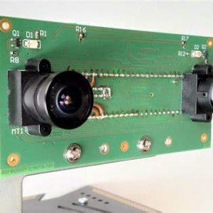
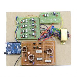
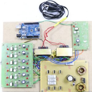
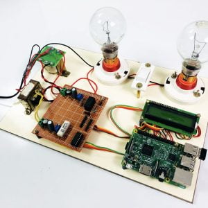
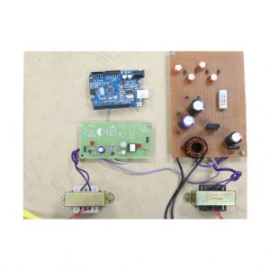
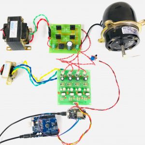
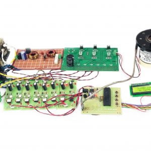
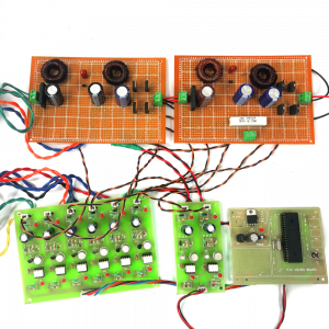
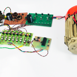
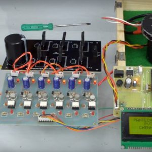
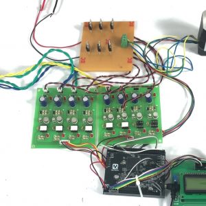
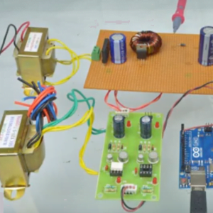
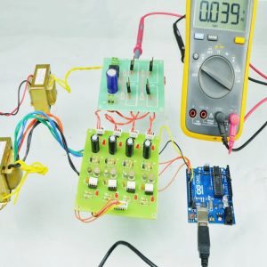
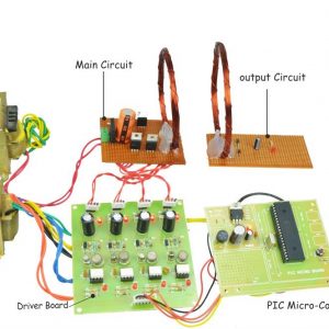
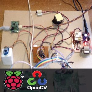
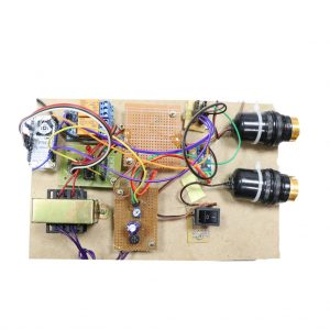
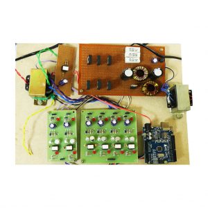
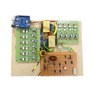
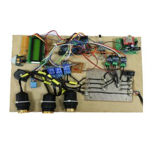
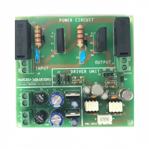
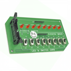
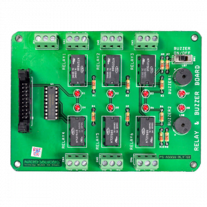
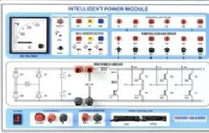
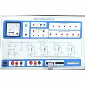
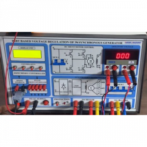
Driver Board

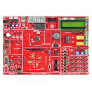
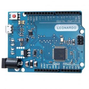
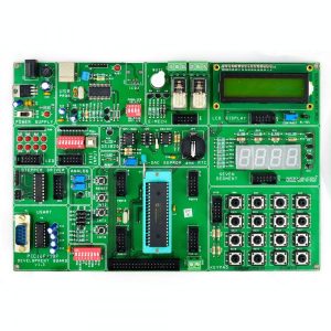
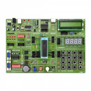
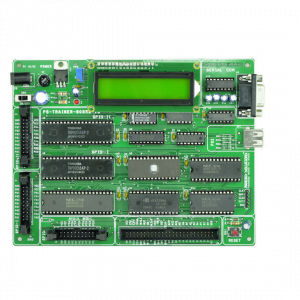
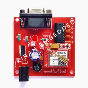
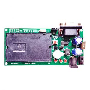
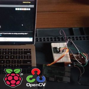
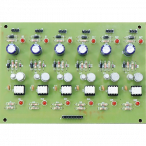
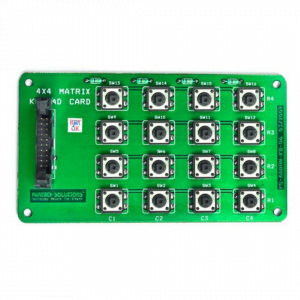
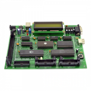
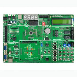
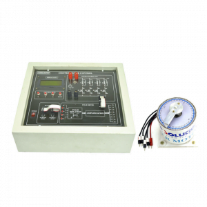
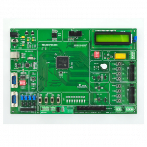
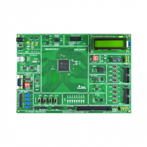
Pic Controller Board

Working:
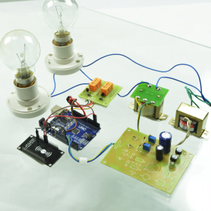
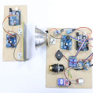
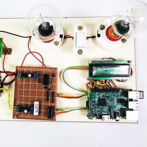
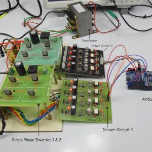
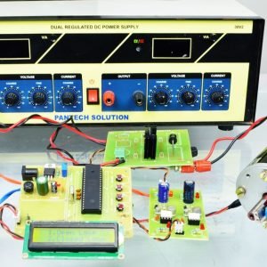
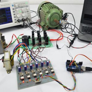
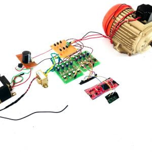
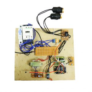
The PIC controller is used to generate the PWM pulses for the converter and inverter circuits. The PIC controller pulses are given to the driver circuit as input. Driver board is mainly used to isolate and amplify the input signals from the controller. The amplified driver output is connected to the main power circuit devices. The ac supply is converted into dc by using a bridge rectifier. And the dc voltage is boosted by using a SEPIC converter. The boosted dc voltage is applied to the inverter circuit and by varying the frequency of the inverter the motor speed also varied.
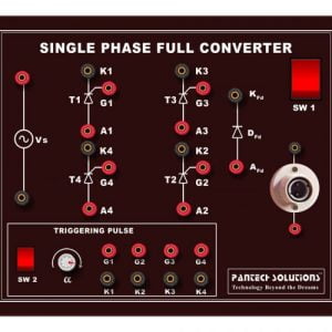
Circuit Diagram For Sepic Converter

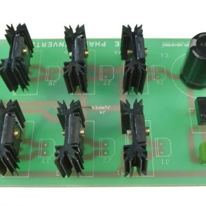
Circuit Diagram For Three Phase Inverter

Advantages
- High efficiency
- Easy to control the speed
- Switching losses are reduced
Applications
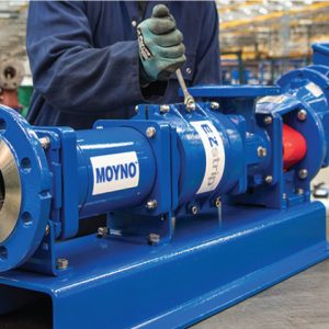
- Industrial applications
- Pumping system
Conclusion
The speed control of a three-phase induction motor by employing a SEPIC converter is mainly used to convert the low voltage sources to useful voltage sources. The solar voltage produced is low voltage and a SEPIC converter is used to boost the low voltage and applied the dc voltage to a three-phase inverter circuit. So that low voltage solar energy is used to control the induction motor speed.
Three Phase Inverter Pattern


Customer Reviews
There are no reviews yet.