


Description
Abstract:
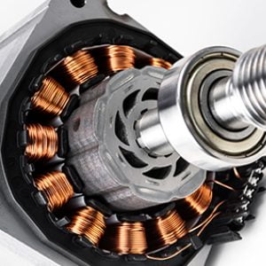
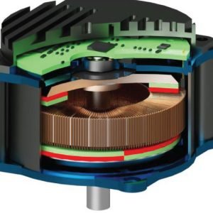
This project is mainly used to control the speed of the BLDC motor by employing a SEPIC Converter Design model. The SEPIC converter is used to step up the input dc voltage. The theSEPIC converter output voltage depends on the duty cycle of the converter. The BLDC motor has high reliability, high-efficiency high torque/inertia ratio, improved cooling, low radio frequency interference, and noise and requires practically no maintenance.?
Introduction:
The SEPIC converter Project exhibits the advantages over the conventional buck, SEPIC, buck-boost, and Cuk converter when employed in SPV-based applications. The SEPIC Converter Design model dc voltage is applied to a three-phase inverter circuit. The three-phase inverter converts the dc voltage into three-phase ac voltage. the converter operates to increase the output voltage.
Proposed System:
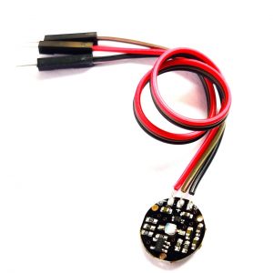
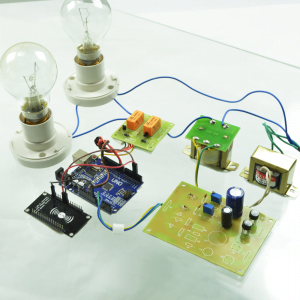
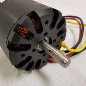
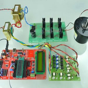
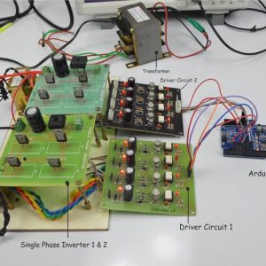
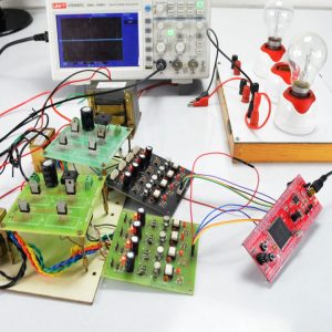
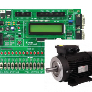
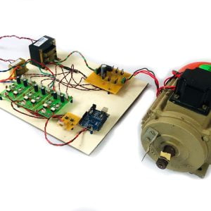
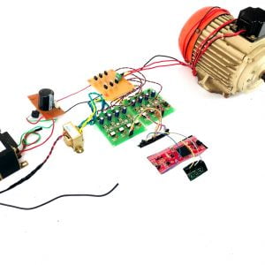
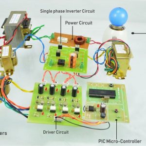
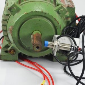
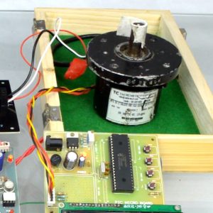
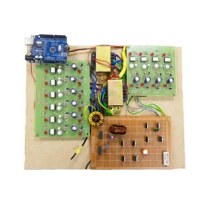
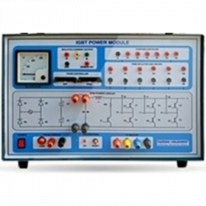
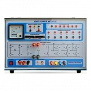
This project is proposed to control the speed of the BLDC motor by employing a SEPIC converter. The AC supply is applied to the bridge rectifier, the bridge rectifier converts ac supply into dc supply. That dc supply is applied to the converter, the converter is SEPIC the input voltage (i.e.) if input 15v dc means the converter output voltage is greater than 15v dc voltage. That dc voltage is given to the three-phase inverter; it converts the dc voltage into three-phase ac voltage. The three-phase ac voltage is connected to the BLDC motor. The bldc motor has a hall sensor.
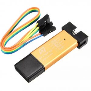
The hall sensor output is feedback to the controller. The three-phase inverter Pulse depends on the hall sensor of the bldc motor. The DSPIC controller key functions are used to control the bldc motor speed.
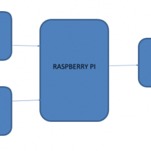
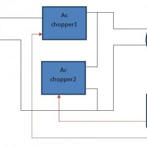
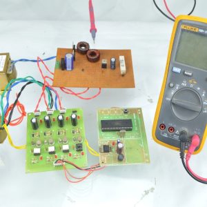
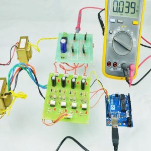
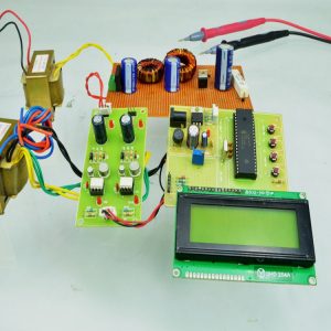
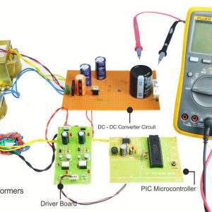
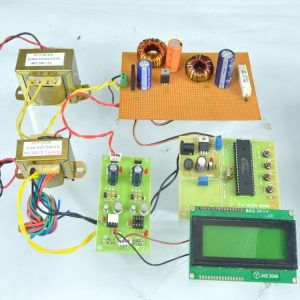
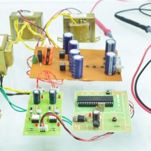
Block Diagram:

Block Diagram Explanation:
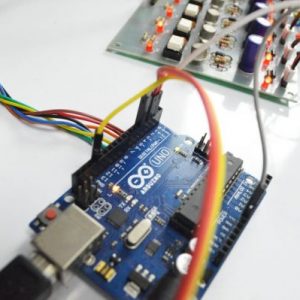
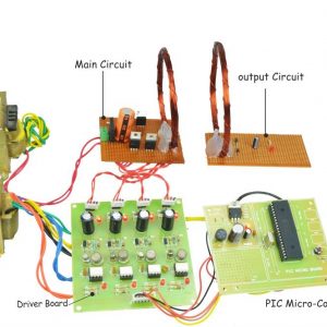
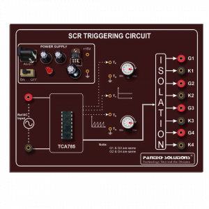
- Pulse generator: ? Here we have used a DSPIC microcontroller (DSPIC 30F4011) to generate a PWM signal.
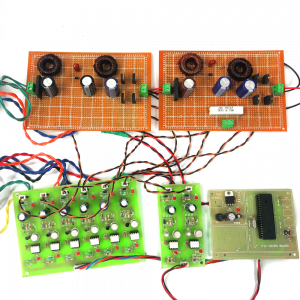
- Driver circuit: -It is used to amplify the pulses and provided isolations using an optocoupler. It has two functions,
- Amplification
- Isolation
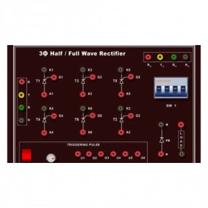
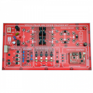
- Bridge Rectifier: It converts AC supply to DC Supply.
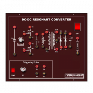
- SEPICconverter: It converts low voltage DC to high voltage DC supply.
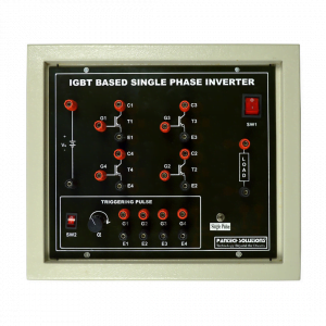
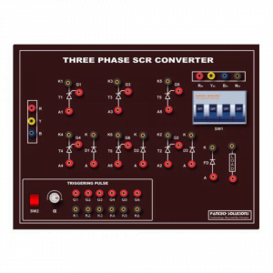
- Three-phase Inverter: It converts DC supplying three phases AC Supply to drive the BLDC motor.
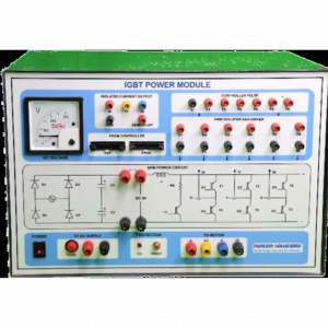
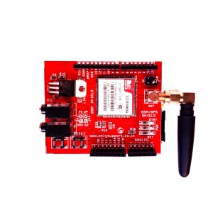
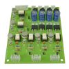
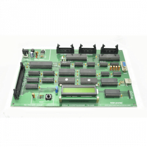
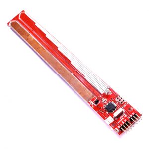
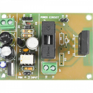
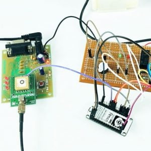
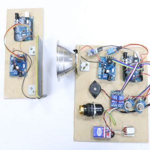
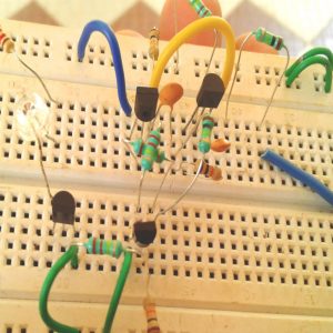
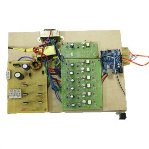
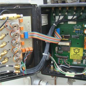
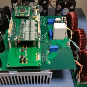
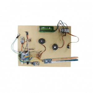
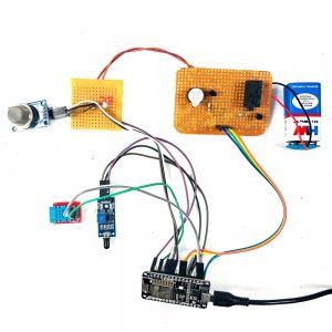
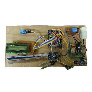
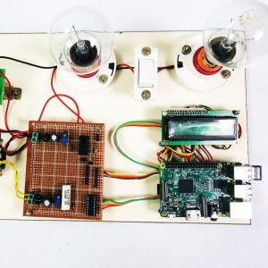
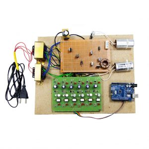
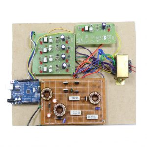
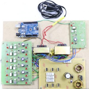
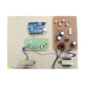
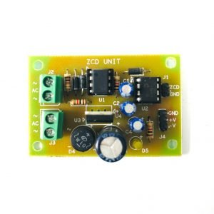
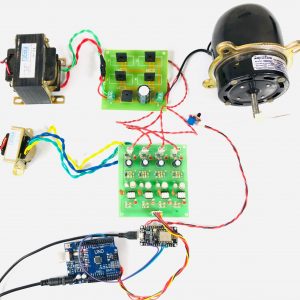
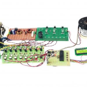
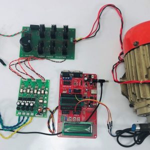
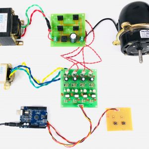
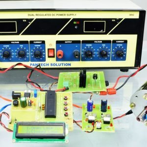
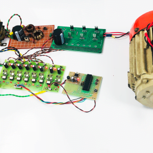
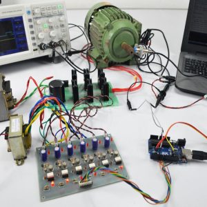
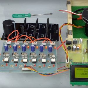
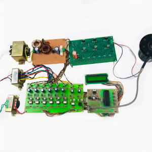
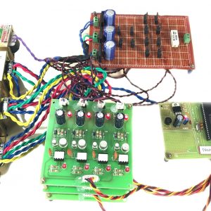
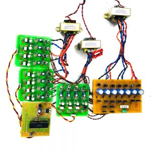
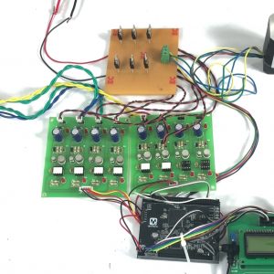
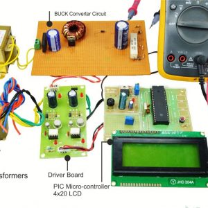
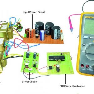
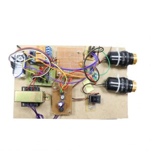
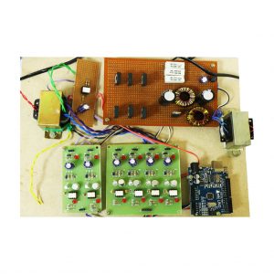
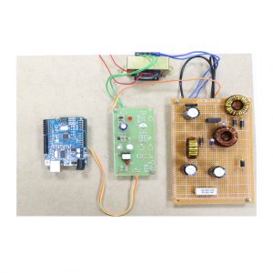
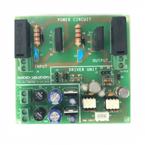
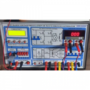
Driver Board:

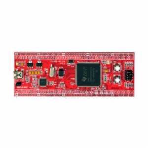
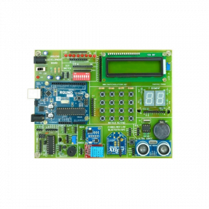
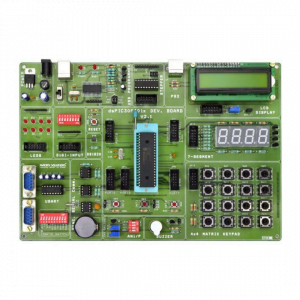
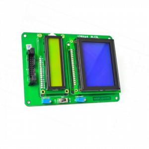
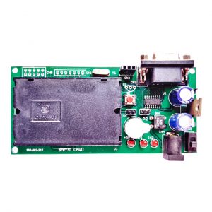
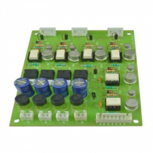
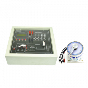
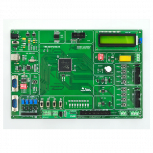
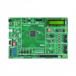
Dspic Controller Board:

Working:
?The DSPIC controller is used to generate the PWM pulses for the converter and inverter circuits. The DSPIC controller pulses are given to the driver circuit as input. Driver board is mainly used to isolate and amplify the input signals from the controller. The amplified driver output is connected to the main power circuit devices. The duty cycle is applied to the SEPIC Converter Design model to vary the output voltage. Three-phase inverter PWM is generated based on Hall sensor feedback.
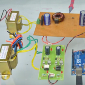
Circuit Diagram For Sepic Converter:

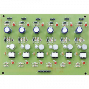
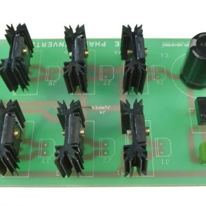
Circuit Diagram For Three Phase Inverter:

- Easy to control the speed
- Highly reliable
- High efficiency and less maintenance
- Less noise
Applications:
- Industrial applications
- Water pumping system
Conclusion:
This project is control the speed of the bldc motor by employing a SEPIC converter and three-phase inverter. This inverter has low switching losses and bldc motor control without any additional control. And also study the response of all characteristics and theory. This project is highly reliable and obtains the high efficiency of this control technique.


Customer Reviews
There are no reviews yet.