

Description
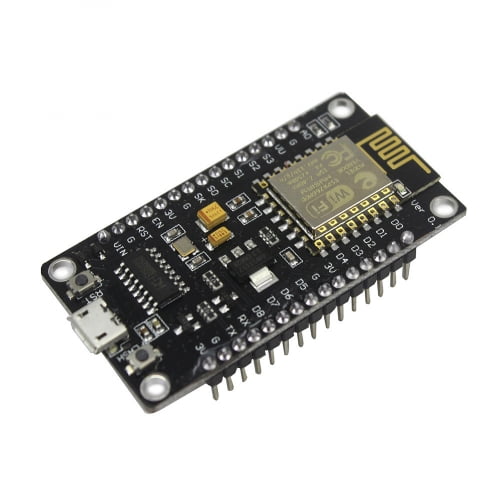
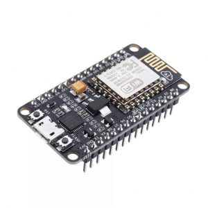
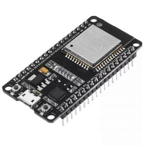
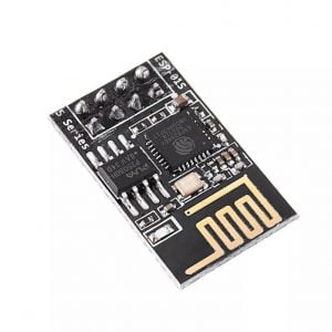
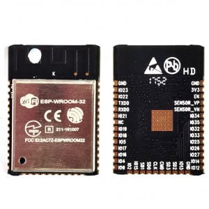
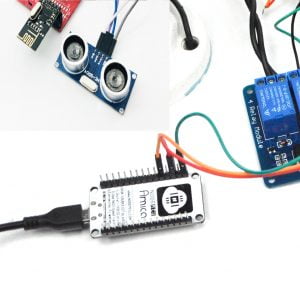
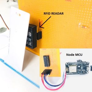
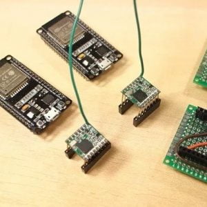
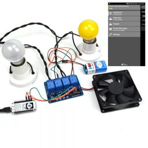
The NodeMCU is a wifi enabled micro controller based on the ESP2866(version 12E) chip. The NodeMCU is low cost and can be programmed using the Arduino IDE. Like other Arduinos, it has GPIO pins that can be used to read sensors and control actuators.?
The NodeMCU is an amazing board that is acceptable on the wallet, however has its downsides.
Driver Installation
One of the downsides of this board is that you need to introduce a usb drivers to speak with this board. You can download the driver from here. Before you attempt to introduce the driver be certain you have Administrator advantages on your PC.
After you have downloaded the driver establishment bundle, and you have Administrator advantages you can begin the establishment. Utilize a Micro USB Type-B link that is evaluated for information move. Follow these means to introduce your Driver
install.PNG
Download Driver
Interface your NodeMCU to your PC utilizing the USB link.
Run the driver establishment bundle you downloaded as Administrator
Snap the introduce button
The driver ought to introduce with no issues. The principle issue that individuals have is either not interfacing the NodeMCU to the PC prior to beginning the introduce, or not having the correct link, or not having the right advantages on your PC. In the event that your driver introduce bombs first ensure all the previously mentioned necessities have been met. On the off chance that it actually doesn’t work you have entered the domain of unsupported freeware, and unfortunately are on an excursion of investigation that can be difficult. I have not seen it bomb when all the prerequisites have been met.
Setting up the Arduino IDE
In the event that you have never worked with an ESP8266 sort of board you need to introduce the drivers and libraries for this in your Arduino IDE. . The individuals at Sparkfun have a decent instructional exercise for this. You go there by tapping on this connection: https://learn.sparkfun.com/instructional exercises/esp8266-thing-hookup-direct/introducing the-esp8266-arduino-addon
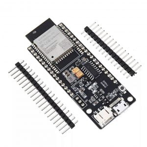
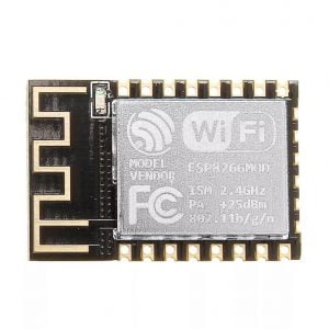
The NodeMCU structure factor
IMG_5031.JPG
You may have seen at this point that the NodeMCU is somewhat huge. It won’t fit on a customary size breadboard (well it does however you have no space to associate anything to it). What I have done to make it fit is utilize a dremel device and cut a typical breadboard in two along the spine (See picture) Now it will fit impeccably.
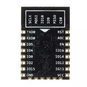
Pinouts
View fullsize
nodemcu_pins.png
This is probably the best downside of the NodeMCU for fledgling clients. The marks on the NodeMCU don’t compare to the advanced pins (GPIO pins) we know and love when working with Arduino compatibles. You need picture ? to sort out it.
For instance nail D1 to the board compares with GPIO 5 (Digital pin 5 on your Arduino). The best activity is keep that picture helpful as a manual for discover what pin does what, and how they compare to the Arduino world.
Specs
The board runs at 3.3v, and everything pins can have a maximum heap of 12mA and a 3.3v rationale. When purchasing breakout sheets or different segments ensure they run on those specs. It additionally implies you must be cautious when utilizing the pins from the NodeMCU to control parts. 12mA isn’t a great deal and this makes it simple for you to over-burden a pin and fry your board. The board additionally has just a single simple port A0, and it is for input just (like any remaining ESP8266).
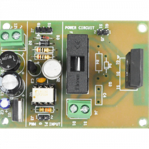
You can control the board with an outer force supply no more noteworthy than 12V. The documentation is competes, yet what I have found is that it can deal with 20V yet the volt controller will get hazardously hot. This is the reason I suggest having a force supply that provisions close to 12V.
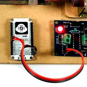
Locally available LED
Frequently we utilize a locally available LED in the improvement stage to mistake check. This board doesn’t have the LED associated with pin/gpio13, rather it has it associated on pin/gpio 2.
Transferring a Sketch
Next we will transfer the flicker sketch to the NodeMCU. On the off chance that you have followed the above advances you ought to have introduced the equipment (driver name) and the Arduino IDE drivers and libraries we are prepared to transfer a flicker sketch.
Arrangement for the NodeMCU
Setup for the NodeMCU
We start by choosing the NodeMCU 1.0 (ESP-12 Module) under the board choices in the Tools menu (See Image for the total design). See Image ? . The lone thing that could be distinctive on your PC is the COM port. You simply need to choose the COM port accessible to you under the Tools menu Port choice.
Underneath you discover the example sketch to make the locally available LED streak on the NodeM
| /** | |
| ?* Blink for Node MCU | |
| ?* also see https://arduino.stackexchange.com/questions/38477/does-the-node-mcu-v3-lolin-not-have-a-builtin-led | |
| ?* | |
| ?* Turns on an LED on for one second, | |
| ?* then off for one second, repeatedly. | |
| ?*/ | |
| #include “Arduino.h” | |
| // On a NodeMCU board the built-in led is on GPIO pin 2 | |
| #define LED_BUILTIN 2 | |
| void setup() | |
| { | |
| ? Serial.begin(14400); | |
| ? // initialize LED digital pin as an output. | |
| ? pinMode(LED_BUILTIN, OUTPUT); | |
| } | |
| void loop() | |
| { | |
| ? Serial.println(“Node MCU blink!”); | |
| ? // turn the LED on (the built-in led on a Node MCU board is active low) | |
| ? digitalWrite(LED_BUILTIN, LOW); | |
| ? // wait for a second | |
| ? delay(1000); | |
| ? // turn the LED off (the built-in led on a Node MCU board is active low) | |
| ? digitalWrite(LED_BUILTIN, HIGH); | |
| ?? // wait for a second | |
| ? delay(1000); | |
| } |


Customer Reviews
There are no reviews yet.