


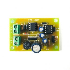
Description
INTRODUCTION
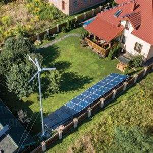
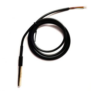
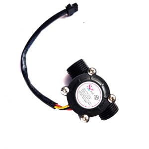
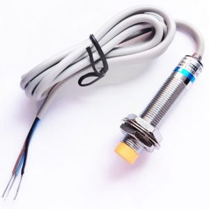
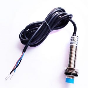
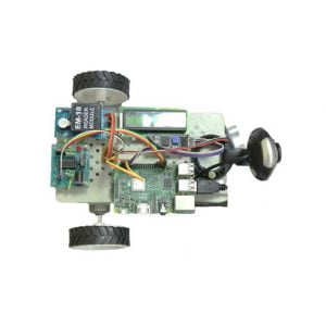
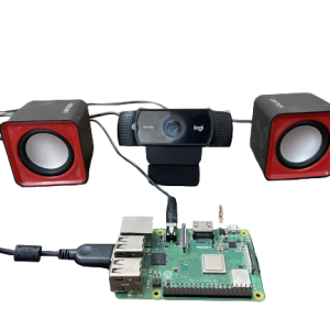
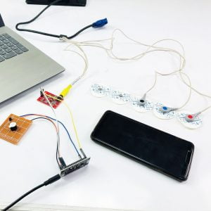
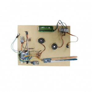
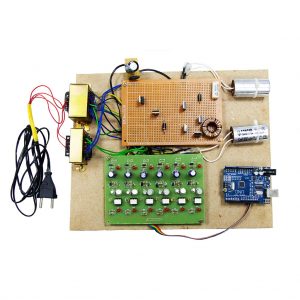
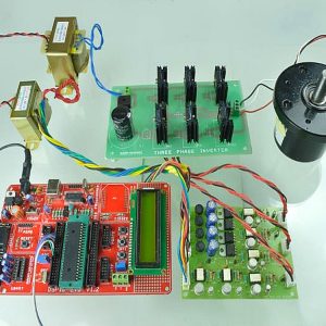
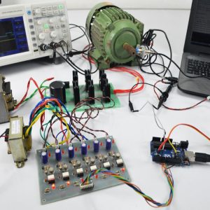
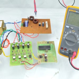
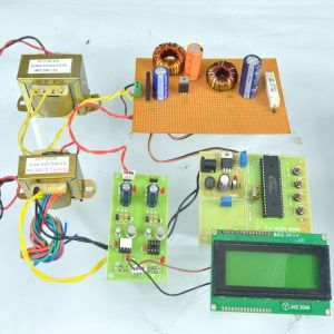
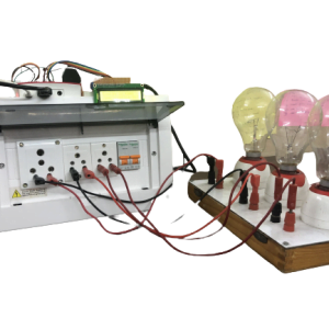
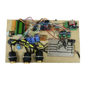
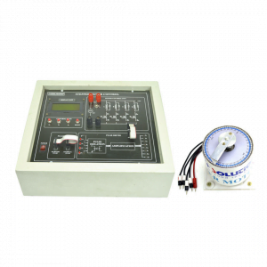
This project describes the speed control of the BLDC motor with the dsPIC Controller (30F4011 Digital Signal Controller) By using the Hall effect sensors of BLDC Motor, the dsPIC30F4011 controller generates the controlled switching pulses for the inverter. The speed control is done by changing the duty cycle of PWM from dsPIC30F4011. The motor speed is measured by using the proximity sensor placed on the BLDC Motor and displayed on LCD.
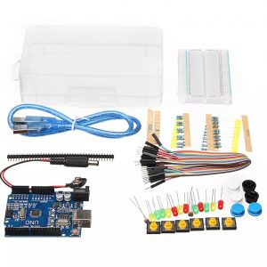
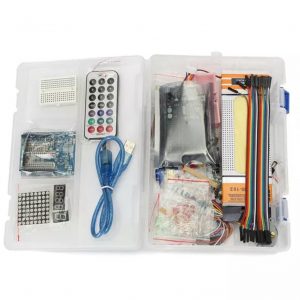
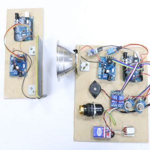
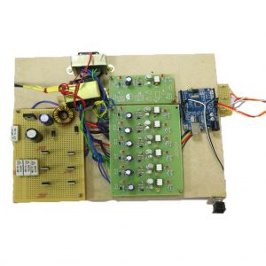
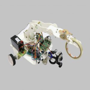
This development kit is used to design and develop a controller for BLDC. All the parts are separately available in the DIY market.
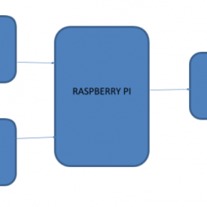
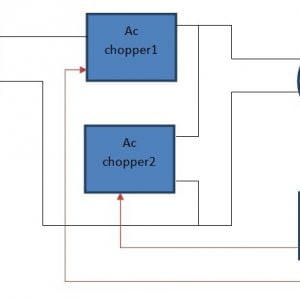
BLOCK DIAGRAM OF BLDC MOTOR SPEED CONTROL

The Hall Effect sensor signals are read from the BLDC motor and fed as inputs to the DSPIC30F4011 device. A 3-bit code can be obtained with values ranging from 1 to 6 by reading the Hall sensor. The duty cycle of the PWM is varied by using a rotational increment push switch. These PWM pulses are enabled based on the 3-bit code getting from the Hall Effect sensor signal. There are six PWM pulses are generated to operate the three-phase inverter. The BLDC Motor speed is adjusted by varying the PWM duty cycle.
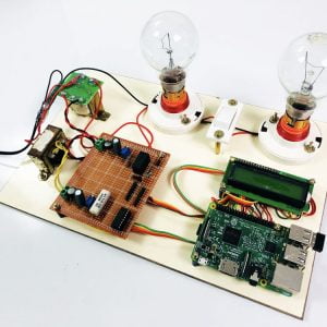
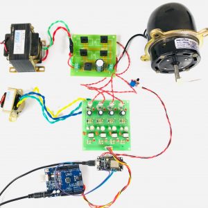
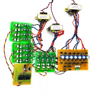
Bundle of Contents
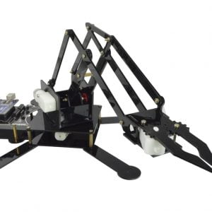
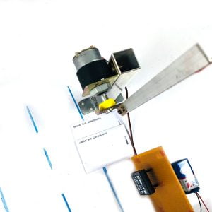
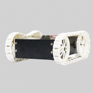
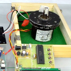
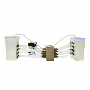
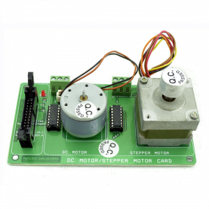
?60W BLDC Motor
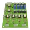
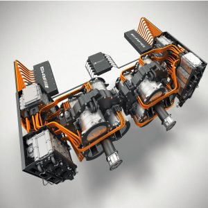
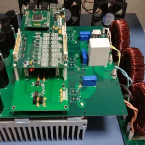
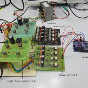
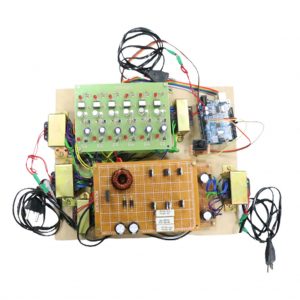
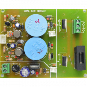
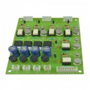
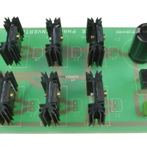
?3Phase Inverter
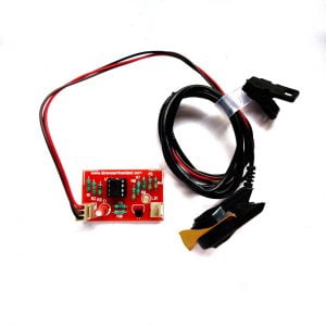
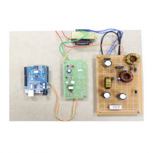
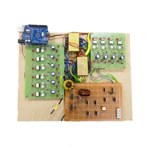
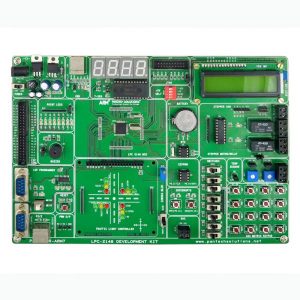
?dSPIC30F4011 Evaluation Board
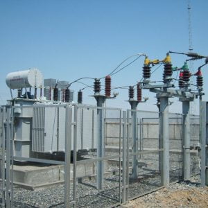
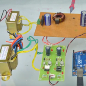
?230/24V, 50Hz Transformer
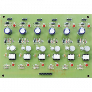
?230/12V, 50Hz for Driver Circuit
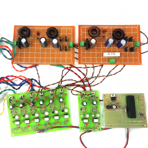
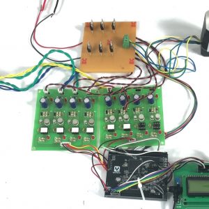
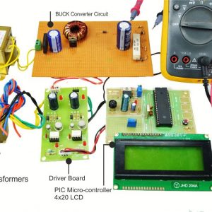
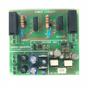
?TLP250 based 3 Leg Driver Board
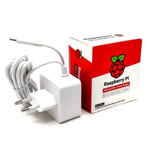
?9V Adaptor
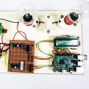
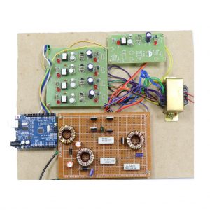
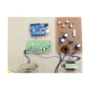
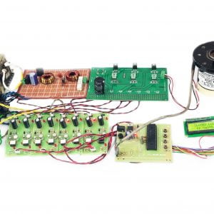
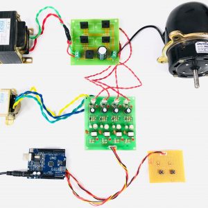
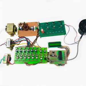
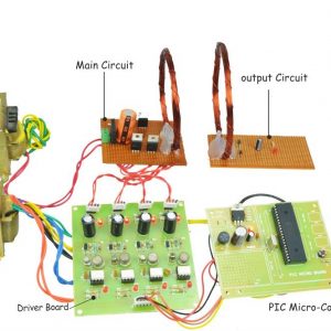
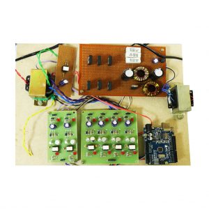
Block Diagram
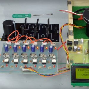
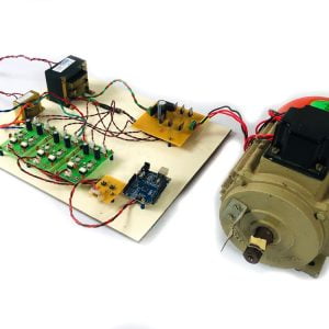
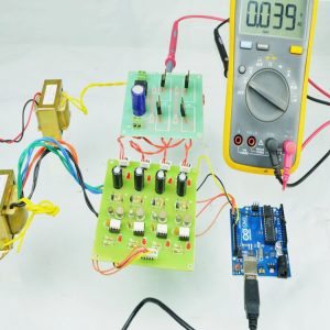
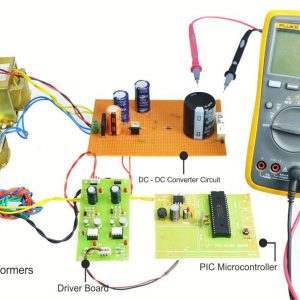
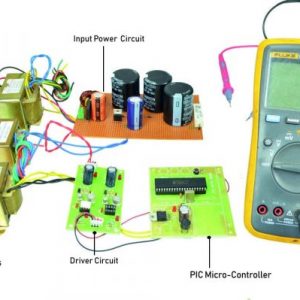
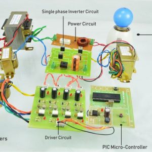
In this project, the BLDC motor is controlled by dSPIC30F4011 DSP Processor. The 24V BLDC Motor power is converted from 24V AC and Full wave rectifier. The 3Ph Inverter circuit formed using IRFP250 MOSFET and its gate is driven by TLP250? with a separate isolator for TOP and BOTTOM MOSFET from dSPIC Processor.

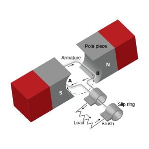
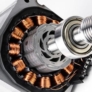
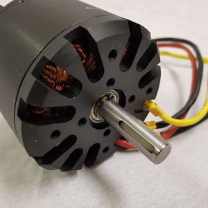
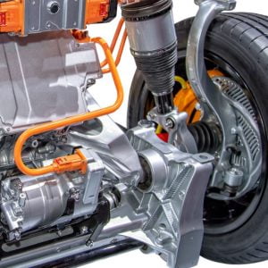
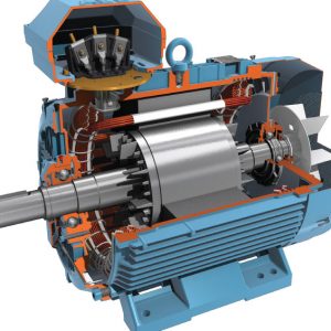
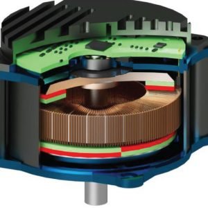
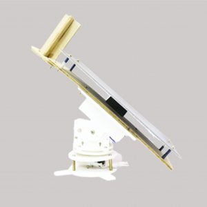
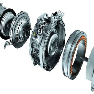
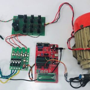
BLDC Motor Specifications

The BLDC Motor is highly reliable and has torque. In industry, the BLDC motor is used widely. The rotor part of the motor is rotated based on the stator excitation.? The entire operation of the BLDC motor can be divided into 6 modes. Each mode has separated by 60 degrees. All the Hall Sensors (A, B, C) are mounted at a 120-degree phase shift. And will be HIGH for 180 degrees of 360-degree rotation.
SPECIFICATION
?Power: 60W
?Voltage: 24V
?Speed: 3000 RPM
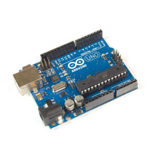
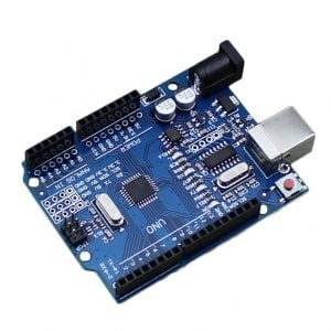
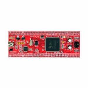
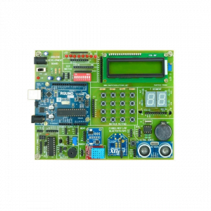
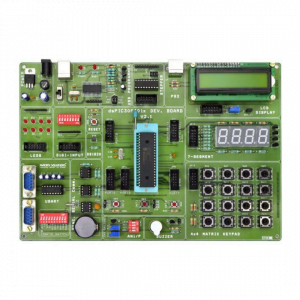
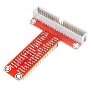
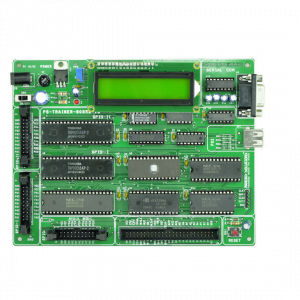
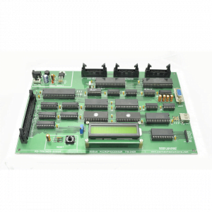
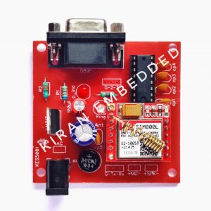
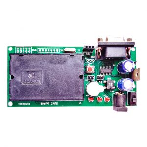
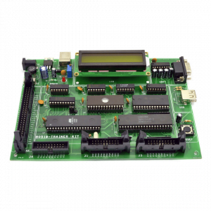
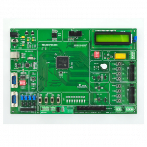
dSPIC30F4011 Evaluation Board

?3 Nos. of switches for interrupt study
?USB 2.0 ISP Programming Facility
?1 No of 10-Pin Expansion Connector
?2 Nos. of 40 Pin Expansion Connector
?On-Board 5V Regulator @ 1.5A
?Reset Circuit
?Power-on LED Indication
?40-pin ZIF Socket for MCU
?2 Nos. of USART (RS232)
?ADC Analog Input (Potentiometer)
?General-purpose area
HALL EFFECT SENSOR SWITCHING SEQUENCE OF INVERTER
A Hall-effect position sensor is used to sense the rotor position on a span of 60?, which is required for the electronic commutation of the BLDC motor. There are six steps are used to cause a full revolution (6 steps x 60? = 360?). For each step, positive position means high side MOSFET on and low side off, negative position means high side MOSFET off and low side on, and neutral position means both MOSFET?s are on.
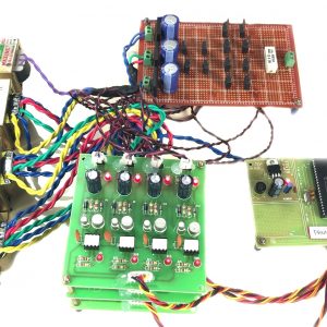
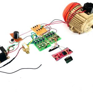
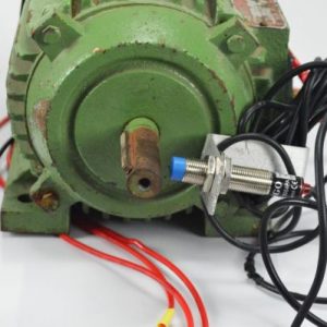
Feedback Block From Motor To Dspic30f4011
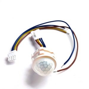
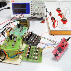
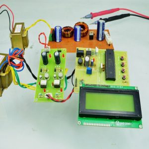
The BLDC Motor’s actual speed is measured in dsPIC30F4011 by using a feedback signal. The feedback signal is getting from BLDC Motor by using a Hall Effect sensor. The dsPIC30F4011 controller displays the motor speed as an RPM value in LCD.
BLDC Motor Speed Control flow
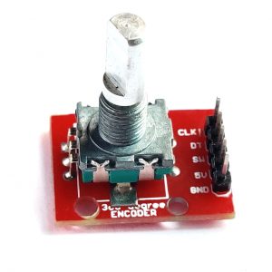
First, Initialize the PWM, Capture, Ports, and Change Notification inputs. After initializing, the capture and change notification pins are read the hall sensor signals. It detects the input signal of the Hall sensor and is allowed it to enable the corresponding phase of PWM pulses. At this point, the motor starts spinning. The Motor speed is varied depending on the PWM duty cycle which is adjusted by using a rotational increment key. The duty cycle and speed measurement values are displayed in LCD.
Steps To Check BLDC Motor Control
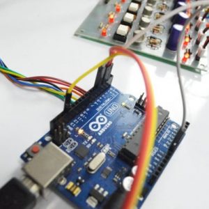
?Connect the Hall Sensor inputs to 5, 6, and 7th?pins of the dsPIC30F4011 controller
?Connect six PWM output signals to BLDC Motor Drive
? Download BLDC inverter. hex file to dsPIC30F4011 controller using MPLAB Software.
? Press the increment button to increase the PWM duty cycle
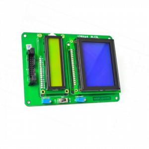
?Display the speed value in RPM in LCD


Customer Reviews
There are no reviews yet.