

Description
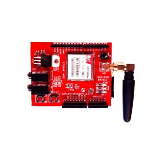
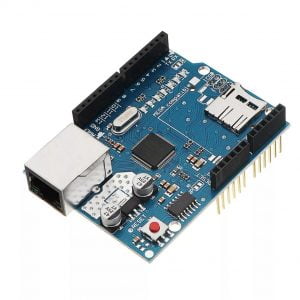
The?Arduino GSM shield?allows an?Arduino?board to connect to the internet, send and receive SMS, and make voice calls using the?GSM?library.
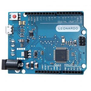
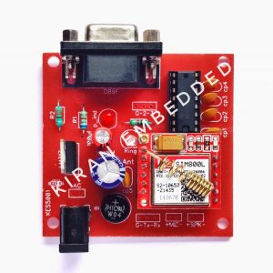
The Arduino GSM Shield V2 connects your Arduino to the net the usage of the GPRS wi-fi network. Just plug this module onto your Arduino board, plug in a SIM card from an operator providing GPRS insurance and comply with a few easy directions to begin controlling your world via the internet. You can additionally make/receive voice calls the use of the on-board audio/mic jack and send/receive SMS messages. As constantly with Arduino, each and every thing of the platform ? hardware, software program and documentation ? is freely accessible and open-source. This skill you can examine precisely how it is made and use its diagram as the beginning factor for your very own circuits. Hundreds of hundreds of Arduino boards are already fuelling people?s creativity all over the world, everyday. Join us now, Arduino is you.
REQUIREMENTS:
- To use the shield, you’ll need to insert a SIM card into the holder. Slide the metal bracket away from the edge of the shield and lift the cradle up.
- Insert the SIM in the plastic holder so the metal contacts are facing the shield, with the notch of the card at the top of the bracket.
- Slide the SIM all the way into the bracket.
- Push the SIM to the board and slide the metal bracket towards the edge of the shield to lock it in place.
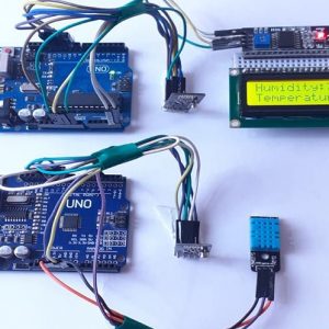
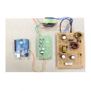
- Once the SIM is inserted, mount it on top of an Arduino board.
- To upload sketches to the board, connect it to your computer with a USB cable and upload your sketch with the Arduino IDE. Once the sketch has been uploaded, you can disconnect the board from your computer and power it with an external power supply.
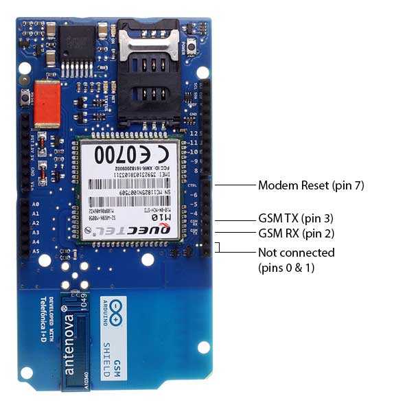
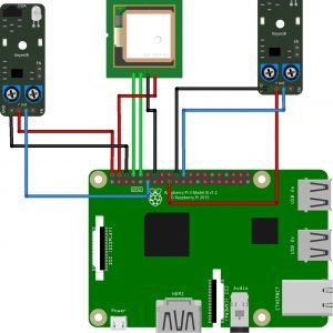
- Digital pins 2, 3 and 7 are reserved for communication between the Arduino and modem and cannot be used by your sketches. Communication between the modem and Arduino is handled by the Software Serial library on pins 2 and 3. Pin 7 is used for the modem reset.
- When the yellow?statusLED turns on, it means the modem is powered, and you can try connecting to the network.
- Developer versions of the GSM shield required you to press press the?Powerbutton on the shield for a few moments to turn the modem on. If you have an early version of the shield, and it does not turn on automatically, you can solder a jumper to the CTRL/D7 pad on the reverse side of the board, and it will turn on when an attached Arduino receives power.
- The shield should work in any area with GSM coverage. Before buying the shield please verify that there is this kind of coverage where you plan to use it.
// import the GSM library
#include <GSM.h>
// PIN Number
#define PINNUMBER “”
// initialize the library instance
GSM gsmAccess(true);???? // include a ‘true’ parameter for debug enabled
GSMScanner scannerNetworks;
GSMModem modemTest;
// Save data variables
String IMEI = “”;
// serial monitor result messages
String errortext = “ERROR”;
void setup()
{
// initialize serial communications
Serial.begin(9600);
Serial.println(“GSM networks scanner”);
scannerNetworks.begin();
// connection state
boolean notConnected = true;
// Start GSM shield
// If your SIM has PIN, pass it as a parameter of begin() in quotes
while(notConnected)
{
if(gsmAccess.begin(PINNUMBER)==GSM_READY)
notConnected = false;
else
{
Serial.println(“Not connected”);
delay(1000);
}
}
// get modem parameters
// IMEI, modem unique identifier
Serial.print(“Modem IMEI: “);
IMEI = modemTest.getIMEI();
IMEI.replace(“\n”,””);
if(IMEI != NULL)
Serial.println(IMEI);
// currently connected carrier
Serial.print(“Current carrier: “);
Serial.println(scannerNetworks.getCurrentCarrier());
// returns strength and ber
// signal strength in 0-31 scale. 31 means power > 51dBm
// BER is the Bit Error Rate. 0-7 scale. 99=not detectable
Serial.print(“Signal Strength: “);
Serial.print(scannerNetworks.getSignalStrength());
Serial.println(” [0-31]”);
}
void loop()
{
// scan for existing networks, displays a list of networks
Serial.println(“Scanning available networks. May take some seconds.”);
Serial.println(scannerNetworks.readNetworks());
// currently connected carrier
Serial.print(“Current carrier: “);
Serial.println(scannerNetworks.getCurrentCarrier());
// returns strength and ber
// signal strength in 0-31 scale. 31 means power > 51dBm
// BER is the Bit Error Rate. 0-7 scale. 99=not detectable
Serial.print(“Signal Strength: “);
Serial.print(scannerNetworks.getSignalStrength());
Serial.println(” [0-31]”);
}


Customer Reviews
There are no reviews yet.